Supercharge Your Innovation With Domain-Expert AI Agents!

Power regeneration device for working machinery

A technology for operating machinery and regeneration devices, which is applied to electromechanical devices, fluid pressure actuating devices, mechanical equipment, etc., can solve problems such as failure to regenerate, complicated operation of changing operation modes, and achieve a good sense of operation

Active Publication Date: 2015-11-25
NIHON KENKI CO LTD
View PDF9 Cites 0 Cited by
  • Summary
  • Abstract
  • Description
  • Claims
  • Application Information

AI Technical Summary

Problems solved by technology

However, in this hydraulic excavator, since the operator cannot perform regeneration without switching the operation mode, there is a possibility that regeneration cannot be performed when it should be performed due to the complexity of changing the operation mode.

Method used


Image

  • Power regeneration device for working machinery
  • Power regeneration device for working machinery
  • Power regeneration device for working machinery

Examples


Embodiment Construction

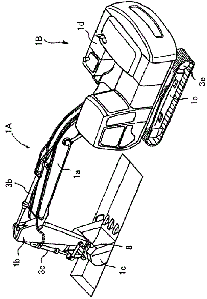
[0023] Embodiments of the present invention will be described below using the drawings. figure 1 It is an external view of a hybrid hydraulic excavator according to an embodiment of the present invention. The hydraulic excavator shown in the figure includes: a articulated working device 1A including a boom 1a, an arm 1b, and a bucket 1c; and a vehicle body 1B including an upper revolving body 1d and a lower traveling body 1e. The boom 1a is rotatably supported by the upper swing body 1d, and is driven by a boom cylinder (hydraulic cylinder) 3a.

[0024] The arm 1b is rotatably supported by the boom 1a, and is driven by an arm hydraulic cylinder (hydraulic cylinder) 3b. The bucket 1c is rotatably supported by the arm 1b, and is driven by a bucket hydraulic cylinder (hydraulic cylinder) 3c. The upper rotating body 1d is driven by a rotating motor (electric motor) 16 (refer to figure 2 ) is rotationally driven, and the lower traveling body 1e is driven by the left and right t...


PUM


Abstract

Disclosed is a motive power regeneration system for a working machine. The motive power regeneration apparatus includes a regeneration circuit (53) that is connected to a hydraulic line (51) through which a returning fluid of a boom cylinder (3A) is distributed during a boom lowering operation and provided with a hydraulic motor (24) connected to a generator (25), a flow regulating circuit (54) that is connected to the hydraulic line (51) and provided with a control valve (5A), an inverter (26) that controls the flow rate on the regeneration circuit (53) in accordance with a first flow rate setting (Q2) which varies with the operation amount of an operating apparatus (4A), and a control valve (5A) and a proportional valve (27) that control the flow rate on the flow regulating circuit (54) in accordance with a second flow rate setting (Q1) which varies with the operation amount of the operating apparatus (4A). Therefore, the motive power regeneration apparatus is capable of making an operator constantly feel comfortable with machine operations.

Description

technical field [0001] The invention relates to an energy regeneration device for working machines such as construction machines. Background technique [0002] In recent years, there has been an increasing demand for improvement in fuel consumption (fuel efficiency) of hydraulic working machines including hydraulic excavators. [0003] For example, Japanese Patent Application Laid-Open No. 2003-329012 discloses a hydraulic excavator having an oil passage connected to a hydraulic chamber on the bottom side of a boom hydraulic cylinder (hydraulic cylinder) and through which return oil flows when the boom is lowered. A switching valve is provided on the (return oil passage), and a regenerative circuit including a hydraulic motor and a generator connected to the hydraulic motor is connected to the downstream side of the switching valve. In this hydraulic excavator, the switching position of the switching valve can be switched according to the operation mode selected on the moni...

Claims


Application Information

Patent Timeline
Patent Type & Authority Patents(China)
IPC IPC(8): F15B21/14E02F9/20E02F9/22F15B11/08
CPCH02K7/1853E02F9/2075E02F9/2091E02F9/2217E02F9/2285F15B11/024F15B21/14F15B2211/353F15B2211/6654F15B2211/761E02F9/20F15B11/08
Inventor 藤岛一雄园田光夫土方圣二
Owner NIHON KENKI CO LTD
Features
  • R&D
  • Intellectual Property
  • Life Sciences
  • Materials
  • Tech Scout
  • Unparalleled Data Quality
  • Higher Quality Content
  • 60% Fewer Hallucinations
Learn More