Fluid valve

A technology of fluid and fluid circulation, which is applied in the field of circulating valves, can solve the problems of increasing influence, and achieve the effect of improving sealing and maintaining control

Inactive Publication Date: 2013-03-13
VALEO SYST DE CONTROLE MOTEUR
View PDF8 Cites 0 Cited by
  • Summary
  • Abstract
  • Description
  • Claims
  • Application Information

AI Technical Summary

Problems solved by technology

[0006] Another difficulty relates to the power that must be applied to the flap in order to move it from its closed position
This power needs to be kept limited in order to reduce the energy consumption of the valve, while the implemented solutions to improve the sealing create friction which has the effect of increasing the required power

Method used


Image

  • Fluid valve
  • Fluid valve
  • Fluid valve

Examples


Embodiment Construction

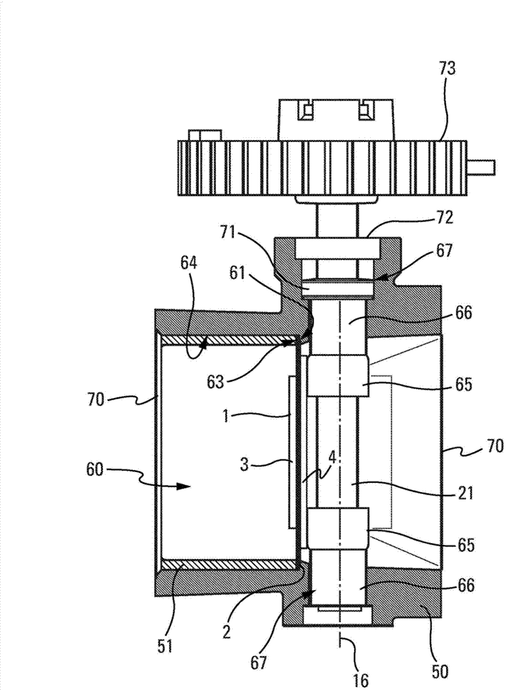
[0031] like figure 1 As shown, the valve according to the invention comprises a body 50 defining a fluid flow conduit 60, and a flap 1 capable of being in a closed position preventing fluid from circulating in the conduit and allowing fluid to circulate in the conduit. movement between the open positions. In this figure, seen from the side, the flap 1 is in the closed position. The valve has a first and a second inlet / outlet hole 70 for fluid, which are located on either side of the conduit 60 .

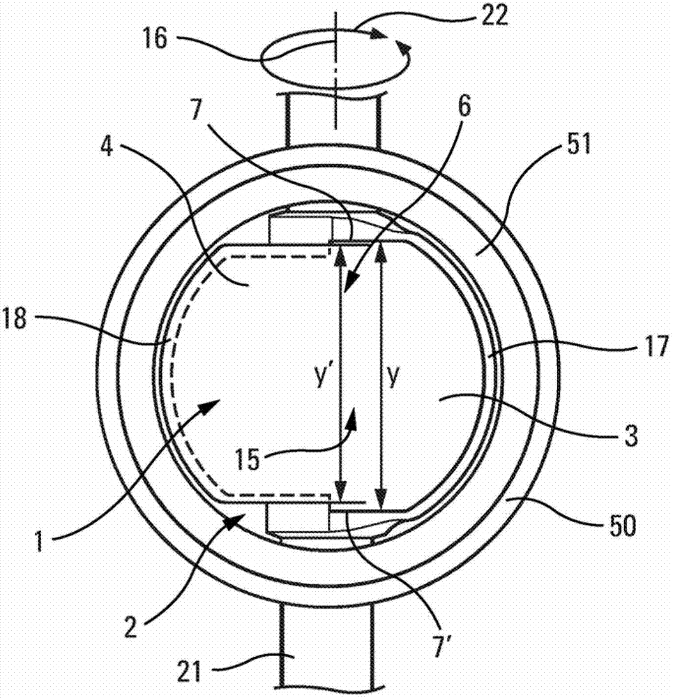
[0032] According to the invention, said valve also comprises a seal 2 having at least one opening 5 for the passage of fluid ( Figure 4 ), and said flap 1 is designed to close said opening or openings 5 ​​in the seal when it is in the closed position.

[0033] This then yields a solution that provides a good seal while limiting friction.

[0034] Said seal 2 is fixed in a fluid-tight manner, for example, to the body 50 of the valve. In particular, it is positioned normal to sai...


PUM


Abstract

The invention relates to a fluid valve comprising: a body (50) defining a fluid flow duct (60), and a flap (1) that can move between a closed position preventing the fluid from flowing through the duct and an open position allowing the fluid to flow through the duct. According to the invention, the valve also comprises a joint (2) having at least one opening for the passage of the fluid, and the aforementioned flap can close the opening(s) (5) in the joint when in the closed position.

Description

technical field [0001] The invention relates to a valve for the circulation of fluids. In particular, the fluid may be exhaust gas from a motor vehicle engine, fresh air leading to the intake side of the engine or a mixture of fresh air and exhaust gas. [0002] The valve can also be used as a metering valve by being placed along the exhaust gas recirculation line or the air intake line between the exhaust port and the intake port of the engine. Background technique [0003] Currently known are valves comprising a body defining a fluid flow conduit and flaps movable between a closed position and an open position, the closed position preventing circulation of the fluid in the conduit, The open position allows circulation of fluid in the conduit. [0004] One difficulty in controlling valves of this type is obtaining satisfactory fluid tightness when the flaps are in the closed position. This is due to the fact that the allowable leak flow rate may be very small. Numerous ...

Claims


Application Information

Patent Timeline
IPC IPC(8): F16K1/226F16K27/02F02D9/10F02M25/07
CPCF02D9/106F02D9/1015Y02T10/121F02M25/0793F16K1/2263F16K27/0218F02M26/70F02D9/10F16K1/226F16K27/02F16K1/22Y02T10/12
Inventor S.阿德诺特G.霍德伯格
Owner VALEO SYST DE CONTROLE MOTEUR
Why Eureka
Try Eureka