Injection pump

A technology of injection pump and pump body, which is applied in the direction of fuel injection pump, fuel injection device, engine components, etc., to achieve the effect of sealing improvement

Active Publication Date: 2013-07-31
WARTSILA FINLAND OY
View PDF8 Cites 0 Cited by
  • Summary
  • Abstract
  • Description
  • Claims
  • Application Information

AI Technical Summary

Problems solved by technology

However, the construction of EP0715070A1 presents weaknesses with regard to fluid flow between the chambers in which the piston member is arranged
There is also the problem of effective sealing with this construction

Method used


Image

  • Injection pump
  • Injection pump
  • Injection pump

Examples


Embodiment Construction

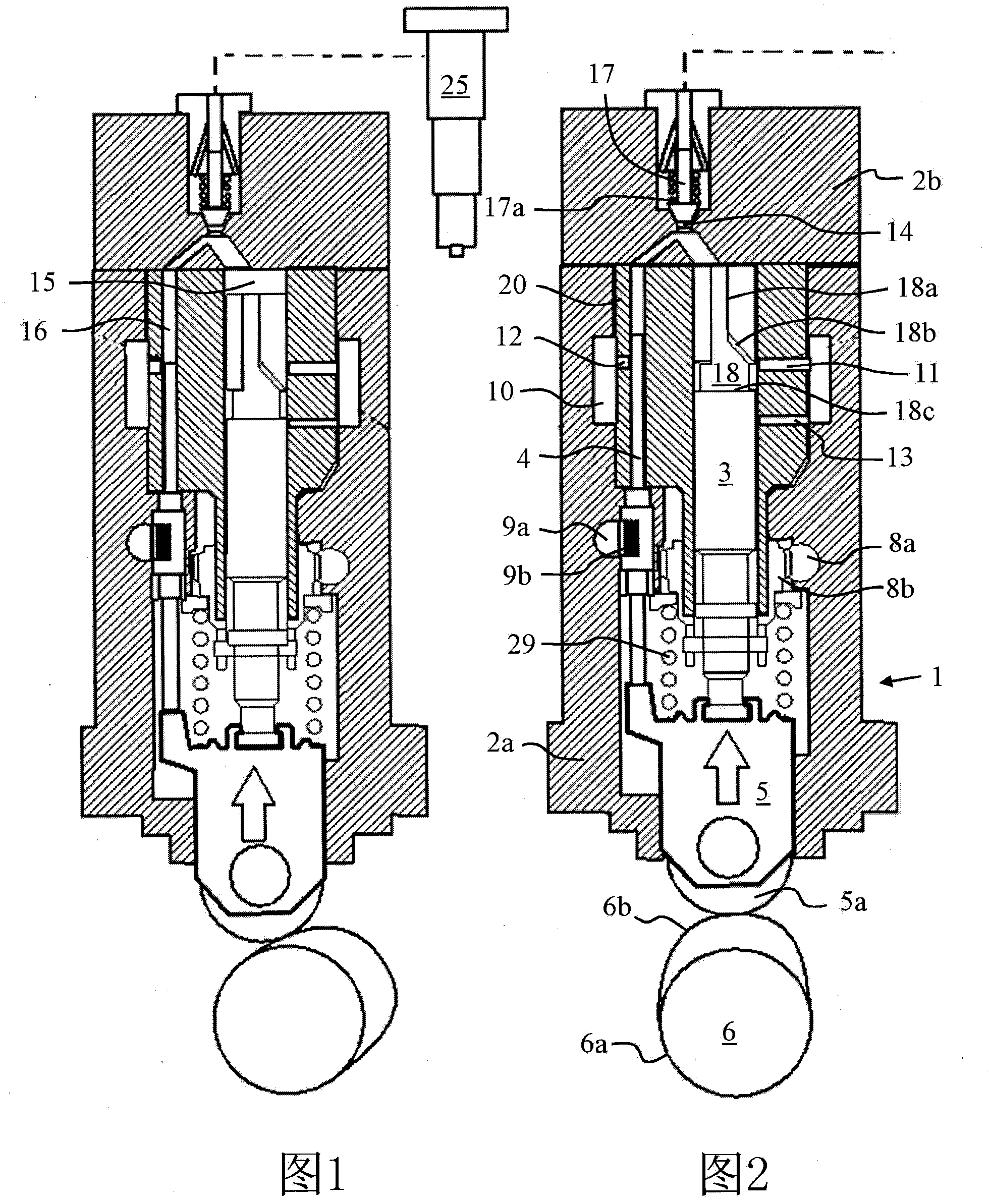
[0029] Embodiments of the present invention will now be described in detail with reference to the accompanying drawings. The jet pump 1 according to one embodiment of the invention is figure 1 and figure 2 shown in . The pump 1 is used to pressurize a fluid, such as fuel, which is injected through a nozzle 25 into, for example, a cylinder of an internal combustion engine. The jet pump 1 includes a pump body 2 . The pump body 2 is formed of a lower body portion 2a and an upper body portion 2b. Inside the pump body 2, an inner body portion 20 is provided. The cylindrical space within the inner body 20 forms the first fluid chamber 15 . There is another cylindrical space within the inner body 20 forming the second fluid chamber 16 . The reciprocating first plunger 3 extends into the first fluid cavity 15 , and the second plunger 4 extends into the second fluid cavity 16 . The first plunger 3 is attached to a thrust device 5 reciprocatable inside the pump body 2 . The thr...


PUM


Abstract

An injection pump (1) for an internal combustion engine, comprising a pump body (2), a first fluid chamber (15) and a second fluid chamber (16) inside the pump body (2) in mutual fluid communication, a first reciprocating plunger (3) protruding into the first fluid chamber (15), a second plunger (4) at least partly inside the second fluid chamber (16), a first fluid port (11) in fluid communication with the first fluid chamber (15)and a second fluid port (12) influid communication with the second fluid chamber (16).A fluid supply channel (10)isin fluid communication with the first fluid chamber (15) and / or the second fluid chamber (16) via the first fluid port (11) and / or the second fluid port (12), and a fluid outlet (14) is in fluid communication with the first fluid chamber (15) and / or the second fluid chamber (16). The first plunger (3) and the second plunger (4) have different diameters.

Description

technical field [0001] The invention relates to an injection pump for an internal combustion engine as defined in the preamble of claim 1 . Background technique [0002] As a fuel injection pump for a compression ignition internal combustion engine, an injection pump capable of generating high injection pressure is required. Especially in large internal combustion engines, similar injection pumps can also be used to inject other fluids, such as water to reduce engine emissions. Large internal combustion engines as used herein refer to engines used eg in power plants or as main or auxiliary engines of ships. [0003] Patent application EP0715070A1 discloses an injection pump for injecting pressure medium into cylinders of an internal combustion engine. The pump comprises two reciprocating piston members arranged within a common pump body. The piston members have control edges, so that the control edge of one of the piston members determines the instant of initiation of inj...

Claims


Application Information

Patent Timeline
IPC IPC(8): F02M59/04F02M59/10F02M59/26F02M59/28
CPCF02M59/265F02M59/28F02M59/102F02M59/04F02M59/26F02M59/10
Inventor H·妮娜斯G·里扬菲尔德
Owner WARTSILA FINLAND OY
Why Eureka
Try Eureka