Fill port for a self-priming centrifugal pump, with safety device

A filling port, self-priming pump technology, applied to the parts of the pumping device for elastic fluid, pump components, variable displacement pump parts, etc., can solve problems such as damage to the safety cover, avoid damage, and improve sealing Effect

Inactive Publication Date: 2009-07-29
ENVIROTECH PUMPSYSTEMS INC
View PDF2 Cites 0 Cited by
  • Summary
  • Abstract
  • Description
  • Claims
  • Application Information

AI Technical Summary

Problems solved by technology

Despite these efforts, many damages continue to occur due to design problems with this safety cover

Method used


Image

  • Fill port for a self-priming centrifugal pump, with safety device
  • Fill port for a self-priming centrifugal pump, with safety device
  • Fill port for a self-priming centrifugal pump, with safety device

Examples


Embodiment Construction

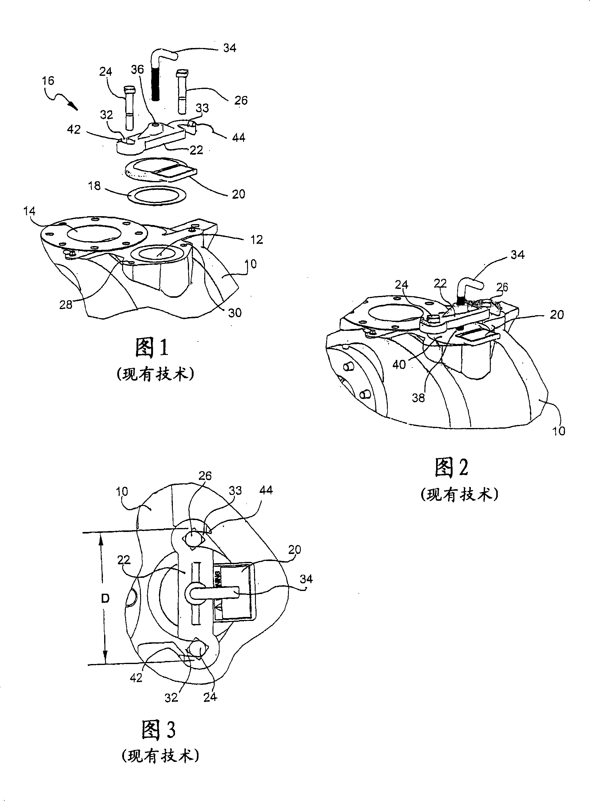
[0021] The filler port safety device of the present invention is best illustrated by comparison with the conventional filler cap shown in FIGS. 1-3. In particular, FIG. 1 shows the top of a pump housing 10 having a fill port 12 disposed near a pump outlet 14 . The closure 16 of the existing filler port 12 includes a flat gasket 18 sized to substantially match the opening of the filler port 12 and held in place by the filler cap 20 . A retaining clip 22 is arranged on the filler cap 20 and is secured to the pump housing 10 by lag bolts 24, 26 threaded into threaded holes 28, 30, wherein the threads in the pump housing 10 Holes 28 , 30 are located on both sides of the filling port 12 . The retaining clip 22 is configured to have U-shaped openings 32 , 33 at its ends for receiving bolts 24 , 26 , respectively.

[0022] An L-shaped anchor bolt 34 is threadedly engaged in retaining clip 22 through central bore 36 . As best shown in FIG. 2 , the filler cap 20 is shown in position...


PUM


Abstract

A safety cover for the fill port of a self-primer pump is structured to improve the seal between the fill port cover and the fill port in the pump casing to thereby control the release of steam from the pump, and includes an improved sealing band between the fill port and fill port cover, an improved fill port cover design and an improved retaining clamp design.

Description

[0001] Cross References to Related Applications [0002] This application is a non-provisional application benefiting from Provisional Patent Application No. 60 / 707097, filed August 10,2005. technical field [0003] The present invention relates to a self-priming centrifugal pump, in particular to a filling port assembly with an improved safety structure. Background technique [0004] Self-priming centrifugal pumps are well known and are often used in industries requiring the handling of fluids that contain solids. Self-priming pumps, also known as trash pumps, are characterized by a housing containing a suction chamber and a separation chamber separated by a wall or plenum. The impeller set in the helical part of the pump receives the fluid from the suction chamber and sends the fluid through centrifugal action to the separation chamber where it finally discharges the fluid through the outlet. [0005] During operation of a self-priming pump, fluid enters the suction cha...

Claims


Application Information

Patent Timeline
IPC IPC(8): F04B53/00
Inventor J·G·肖J·诺斯拉普
Owner ENVIROTECH PUMPSYSTEMS INC
Why Eureka
Try Eureka