Push-pull rotational trenching machine

A slotting machine and rotary technology, which is applied to earth movers/excavators, construction, etc., can solve the problems of low efficiency and high equipment construction costs

Inactive Publication Date: 2013-03-20
浙江省建筑科学设计研究院建筑设计所
View PDF8 Cites 4 Cited by
  • Summary
  • Abstract
  • Description
  • Claims
  • Application Information

AI Technical Summary

Problems solved by technology

[0002] At present, the groove forming machines used in the construction of underground w

Method used


Image

  • Push-pull rotational trenching machine
  • Push-pull rotational trenching machine

Examples


Embodiment Construction

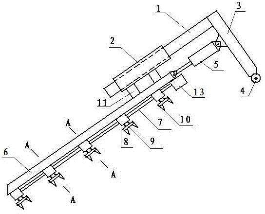
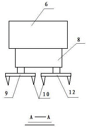
[0012] Accompanying drawing is a kind of specific embodiment of the present invention, and this embodiment column 3 lower end is provided with hinged seat 4, and column upper end is connected with slide bar 1, and slide bar periphery is provided with sliding sleeve 2, and sliding sleeve is fixed on driving by connecting block 11. Rod 6, the right end of the driving rod is hinged to the left end of the driving hydraulic cylinder 5, the right end of the driving hydraulic cylinder is hinged to the column, the lower part of the driving rod is provided with several gear boxes 8, each gear box is connected by a linkage rod, and the lower end of each gear box is provided with a knife Disc A and cutter disc B are provided with a plurality of drill teeth 10 .

[0013] When the present invention is working, the driving motor drives the cutter head A to rotate forward through the linkage rod 7 and the gear box 8, and the cutter head B is reversed. In this way, the drill teeth on the cutt...


PUM


Abstract

The invention relates to a push-pull rotational trenching machine for trenching on basic underground walls of buildings. A hinged support is arranged at the lower end of an upright post; a slide bar is connected to the upper end of the upright post; a sliding bush is arranged on the periphery of the slide bar, and is fixedly arranged on a driving rod through a connecting block; the right end of the driving rod is hinged at the left end of a driving hydraulic cylinder; the right end of the driving hydraulic cylinder is hinged on the upright post; a plurality of gear boxes are arranged on the lower part of the driving rod; the gear box are connected through a linking rod; a cutter head A and a cutter head B are arranged at the lower end of each gear box; and the cutter A and the cutter B are respectively provided with a plurality of drilling teeth.

Description

1. Technical field [0001] The invention relates to a groove forming machine, in particular to a push-pull rotary groove forming machine for building foundation underground walls. 2. Background technology: [0002] At present, the groove forming machines used in the construction of underground walls all have the characteristics of high equipment construction cost and low efficiency. 3. Contents of the invention: [0003] The present invention makes up for the shortcomings of the above slotting machines, and provides a push-pull rotary slotting machine. [0004] The present invention is achieved through the following technical solutions: [0005] A push-pull rotary grooving machine, the lower end of the column is provided with a hinge seat, the upper end of the column is connected with a sliding rod, the outer periphery of the sliding rod is provided with a sliding sleeve, the sliding sleeve is fixed to the driving rod through a connecting block, and the right end of the dr...

Claims


Application Information

Patent Timeline
IPC IPC(8): E02F5/08
Inventor 张永忠
Owner 浙江省建筑科学设计研究院建筑设计所
Why Eureka
Try Eureka