Butterfly helicopter

A helicopter and butterfly technology, applied in the direction of rotorcraft, motor vehicles, aircraft, etc., can solve the problems of poor safety, easy to be attacked by bullets, complicated flight operating system, etc.

Inactive Publication Date: 2018-09-07
姜晓林
View PDF0 Cites 2 Cited by
  • Summary
  • Abstract
  • Description
  • Claims
  • Application Information

AI Technical Summary

Problems solved by technology

Regardless of single-rotor or dual-rotor helicopters, the power transmission system and flight operating system are complex, the engine power loss is large, there are many faults, and the safety is poor. Crashed by hitting surrounding objects, the cabin is under the rotor, once an accident occurs, the crew cannot parachute or escape through the ejection cabin; the cabin facade is large and unarmored, and it is vulnerable to bullets, and it cannot land on water

Method used


Image

  • Butterfly helicopter
  • Butterfly helicopter
  • Butterfly helicopter

Examples


Embodiment Construction

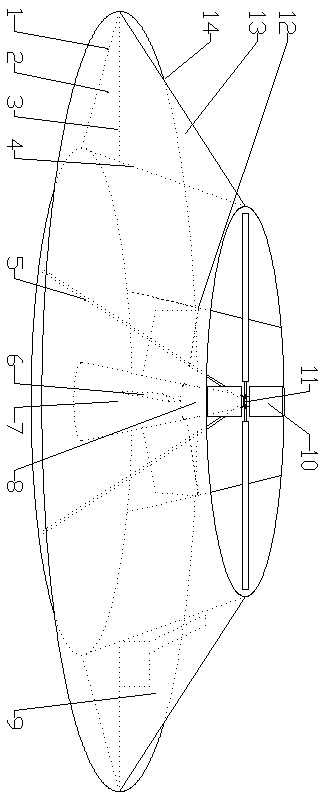
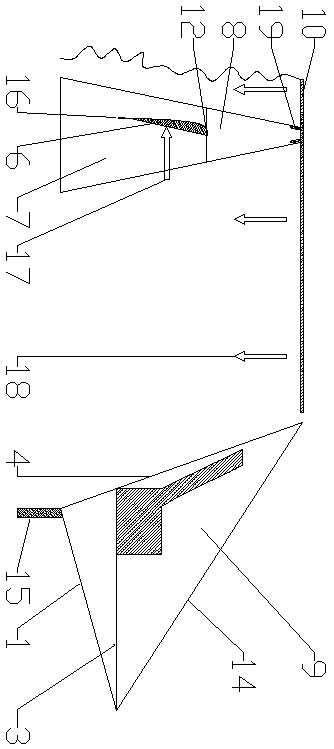
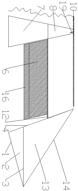
[0012] Such as figure 1 Shown, the rotor 10 is installed on the rotor shaft 11, the outer cover of the rotor shaft 11 is the engine conical radiator 8, below is the engine and transmission conical shell 7, surrounded by the lower cone 1, the upper cone 14 and the inner cone The body 4 constitutes a butterfly cabin, the butterfly cabin and the motor conical radiator 8 are movably connected by three cables 12, and the middle part is connected by three hydraulic rods 12 and the conical shell 7 of the engine and transmission, and the outside of the hydraulic rod 12 is a wing plate 6 , the lower part of the wing plate is the flap 16, such as figure 2 As shown, the rotor 10 produces a downward airflow 18 counterclockwise, and the two sides of the wing plate 6 and the flap 16 produce a clockwise horizontal thrust 17 on the wing plate due to the difference in the speed of the curved surface and the plane airflow on both sides of the flap 16, and the angle of the flap 16 can be adjust...


PUM


Abstract

The invention relates to a butterfly helicopter. The butterfly helicopter is characterized in that three wing plates are vertically installed under a single rotor; downward airflow generated by the rotor allows the wing plates to generate horizontal thrust so as to counteract the reaction force of the rotor; three cones around the rotor compose a butterfly cabin which is connected to a spindle sleeve located on the lower part of the rotor by three inclined pull bars via movable bolts; the upper parts of the wing plates are provided with three horizontal hydraulic rods; the gravity center of the helicopter is moved through telescoping; the rotor inclines so as to generate thrust moving towards one side; and flaps are controlled so as to maintain or change the turning direction of the cabin,so the butterfly helicopter can realize omnibearing flight. The rotor is mounted inside the butterfly cabin and is thus protected, and the conical shells of a generator and a gearbox can reduce powerloss. The armored cabin with a triangular cross section has stealth and protection functions; in the case of falling, the wing plates generate horizontal thrust, which makes the butterfly helicopterglide in airflow; the butterfly helicopter is equipped with a large parachute to prevent crash, and pilots and passengers can escape through an ejection capsule; and the lower parts of the cabin and the engine shell are sealed, so the butterfly helicopter can land on water.

Description

technical field [0001] The present invention relates to butterfly helicopters. Background technique [0002] Current helicopters are divided into single-rotor helicopters and dual-rotor helicopters. Single-rotor helicopters counteract the reaction force generated by the large propeller through the rotation of the tail rotor, and dual-rotor helicopters usually counteract the unbalanced lift generated by the rotors by relatively inverting the rotors. Regardless of single-rotor or dual-rotor helicopters, the power transmission system and flight operating system are complex, the engine power loss is large, there are many faults, and the safety is poor. Collide with surrounding objects and crash, the cabin is below the rotor, in case of an accident, the crew on board cannot parachute or escape through the ejection cabin; Contents of the invention [0003] The invention overcomes the disadvantages of the current helicopter technology and provides a butterfly helicopter. Its ch...

Claims


Application Information

Patent Timeline
IPC IPC(8): B64C27/06B64C27/20
CPCB64C27/06B64C27/20
Inventor 姜晓林
Owner 姜晓林
Why Eureka
Try Eureka