Airplane interior systems

a technology for interior systems and aircraft, applied in aircraft crew accommodation, general lighting, mass transit vehicle lighting, etc., can solve the problems of claustrophobic and limited space in passenger cabins and airplanes, and achieve the effect of maximizing the interest, elegance and ergonomic quality of passenger space, and changing the perception of space inside the passenger cabin

Active Publication Date: 2006-10-26
THE BOEING CO
View PDF34 Cites 100 Cited by
  • Summary
  • Abstract
  • Description
  • Claims
  • Application Information

AI Technical Summary

Benefits of technology

[0005] The present invention provides new and innovative solutions to the present situation on passenger aircraft, particularly the traditional and often outdated “look and feel”. In particular, the invention maximizes the interest, elegance, and ergonomic quality of the passenger space which is available. By changing the interior architectural lines, as well as the lighting and lighting fixtures, the perception of the space inside the passenger cabin is changed and can be altered when desired. For example, the interior architecture and lighting can be changed to cater to different passenger moods and also dramatize the key rituals performed aboard aircraft, such as boarding, resting, eating and the like. Also, different aesthetic and special passenger interests can be provided by changing the architectural structures and lines.
[0007] Secondary panels extending below the ceiling member can act as air diffusers, noise attenuators and light diffusers in order to change the atmosphere and perception of the passenger cabin space and architecture. In order to form a higher ceiling, a curved arch-type ceiling structure is provided, preferably with a constant radius. The ceiling structure begins with subtle concavity of the outboard luggage bins which leads the passenger's eyes up to the crown where a lens is positioned. The lens continues the line of the luggage bins until the unit merges into and is flush with the upper ceiling in an approximately half circle. The lens also diffuses the light and filters it down over the upper ceiling and storage bins onto the secondary panels and further into the cabin.
[0008] For a lower ceiling, a secondary ceiling panel is positioned below the regular ceiling panel and has a look and configuration reminiscent of an airplane wing. The secondary ceiling panel reflects light as well as lets light through softly from a backlit lighting member. By increasing the amount of light that deflects from the secondary ceiling panel and decreasing the amount of light that diffuses from the lens from the crown, the perception can be shifted to simulate a smaller, more nurturing volume. The secondary panel member also permits an exchange between two adjacent passenger cabin spaces. Although the two spaces are different and yet adjacent one another, the two spaces interrelate with one another and can be sensed relative to each other.

Problems solved by technology

In general, the space in the passenger cabins and airplanes is limited and can even be called claustrophobic at times. In this regard, the design and architecture of the interiors of passenger aircraft, particularly the passenger cabins, have remained typically constant for a long period of time and have not had a significant variety of changes or updates as common in many industries.

Method used


Image

  • Airplane interior systems
  • Airplane interior systems
  • Airplane interior systems

Examples


second embodiment

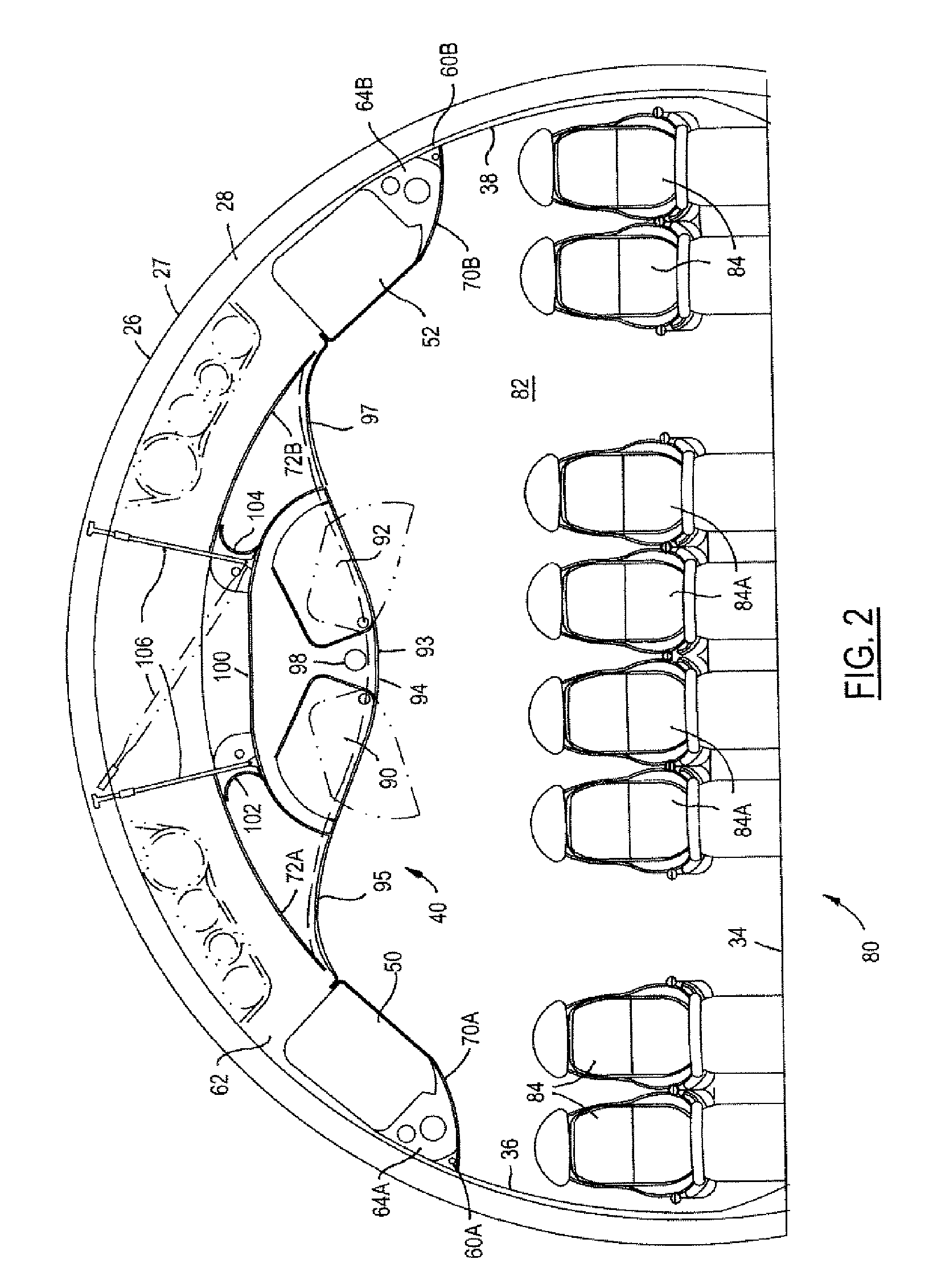
[0041] a passenger cabin structure 82 is shown in FIG. 2 and indicated generally by the reference numeral 80. Passenger cabin 82 has a two-four-two arrangement of passenger seats 84, 84A which indicates that this embodiment has typical application for an “economy” cabin of a passenger aircraft.

embodiment 80

[0042] Many of the structures and systems of the embodiment shown in FIG. 2 are the same as those shown in FIG. 1 and are designated by the same reference numerals. The primary difference is in the central part of the ceiling system 40. In the embodiment 80 shown in FIG. 2, two additional sets or rows of inboard stowage bins 90, 92 are provided for the passengers located in the central rows of passenger seats 84A. The luggage bins 90, 92 are positioned in the ceiling panel assembly 94 which has the approximate shape of the wing of a bird in flight with the “wings” extending outwardly on both sides. The ceiling panel assembly 94 has a concave curved center panel 93 in which the two stowage bins 90, 92 are positioned and two convex curved panels 95 and 97 which are curved to mate smoothly with the curvature of the outboard ceiling panel members 70A, 70 B in which the outboard stowage bins 50, 52 are positioned.

[0043] An additional passenger service unit 98 is positioned in the ceiling...


PUM


Abstract

Interior architectural structures and lighting for aircraft, particularly commercial passenger airplanes. Light diffusers and ceiling panels in a “wing-shape” and other secondary panels are utilized to create different interior designs and structures. A permeable secondary panel is utilized in one passenger cabin in order to provide a more private-type space. An enlarged ceiling arch with blended curves forming a “wing-type” configuration provides a more spacious cabin arrangement. Other features include air and light diffusers, passenger service modules, a “shelf”-like configuration and lighting above the airplane entrance / exit door, and bulkheads and monuments positioned at various positions in the cabin.

Description

TECHNICAL FIELD [0001] The present invention relates to interior systems for aircraft, particularly interior systems for commercial passenger airplanes. BACKGROUND [0002] The interior configuration and architecture of airplanes has become relatively standardized today. The arrangement of the passenger seats, bulkheads, lavoratories, serving areas, and the like have been developed for convenience and accommodation of both passengers and crew. The passenger compartments are typically divided into two or more sections with bulkheads and lavoratories being positioned accordingly. Aisles and passageway spaces are left between sets of seats and at the access doors. [0003] The passenger compartments of aircraft typically have sidewall members with a plurality of windows, a floor panel or member and a ceiling member or assembly of some type. In addition, pluralities of rows of storage bins are positioned on the aircraft generally at the position between the sidewall members and the ceiling ...

Claims


Application Information

Patent Timeline
Patent Type & Authority Applications(United States)
IPC IPC(8): B64D11/00
CPCB60Q3/025B64D11/00B64D2011/0046B64D2011/0038B64D11/003B60Q3/43
Inventor LAU, CHARLES K.TRUMMER, JULIANE B.
Owner THE BOEING CO
Why Eureka
Try Eureka