
Aeroengine nacelle

Active Publication Date: 2006-08-15
ROLLS ROYCE PLC
View PDF4 Cites 91 Cited by
  • Summary
  • Abstract
  • Description
  • Claims
  • Application Information

AI Technical Summary

Benefits of technology

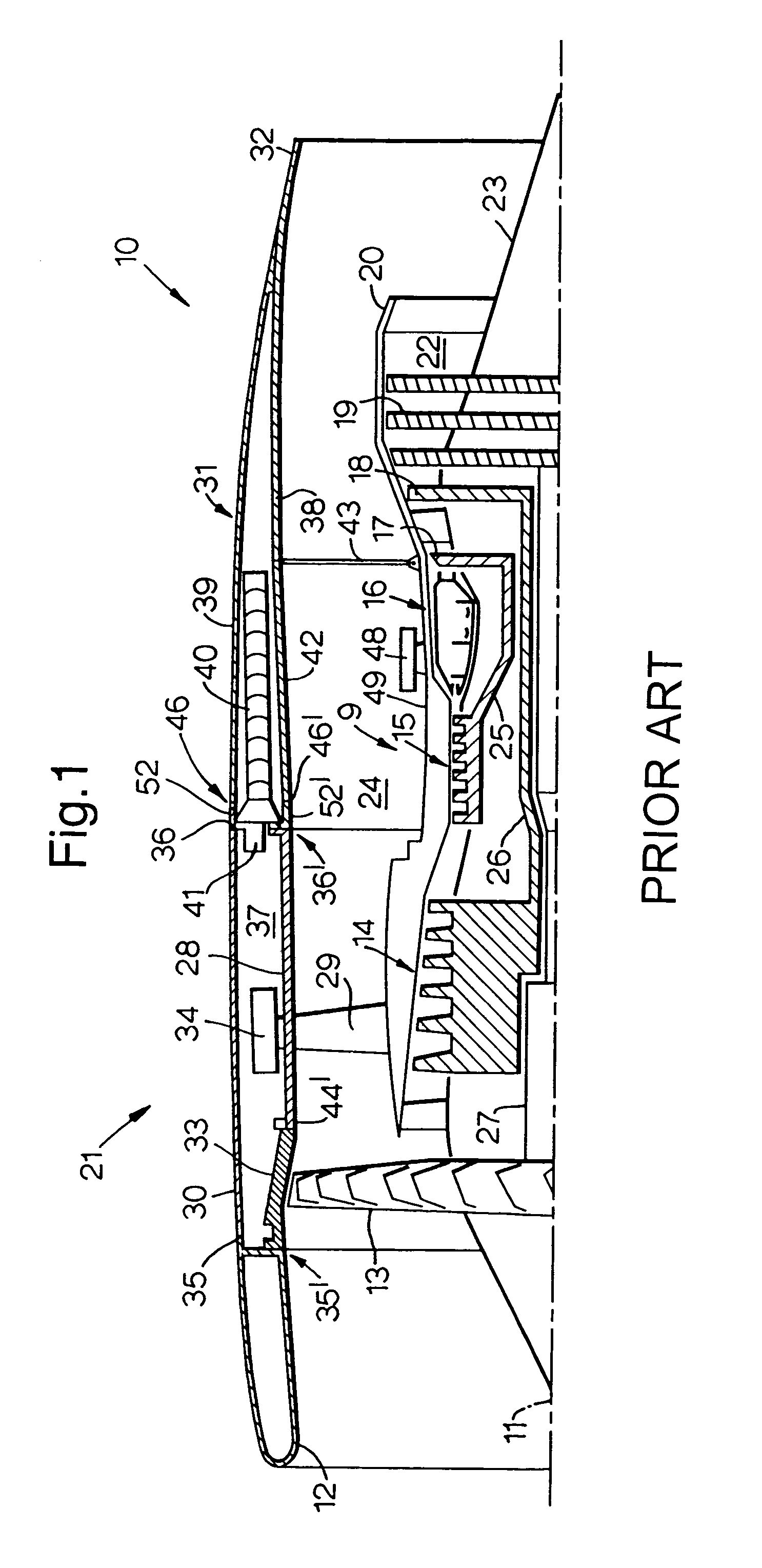
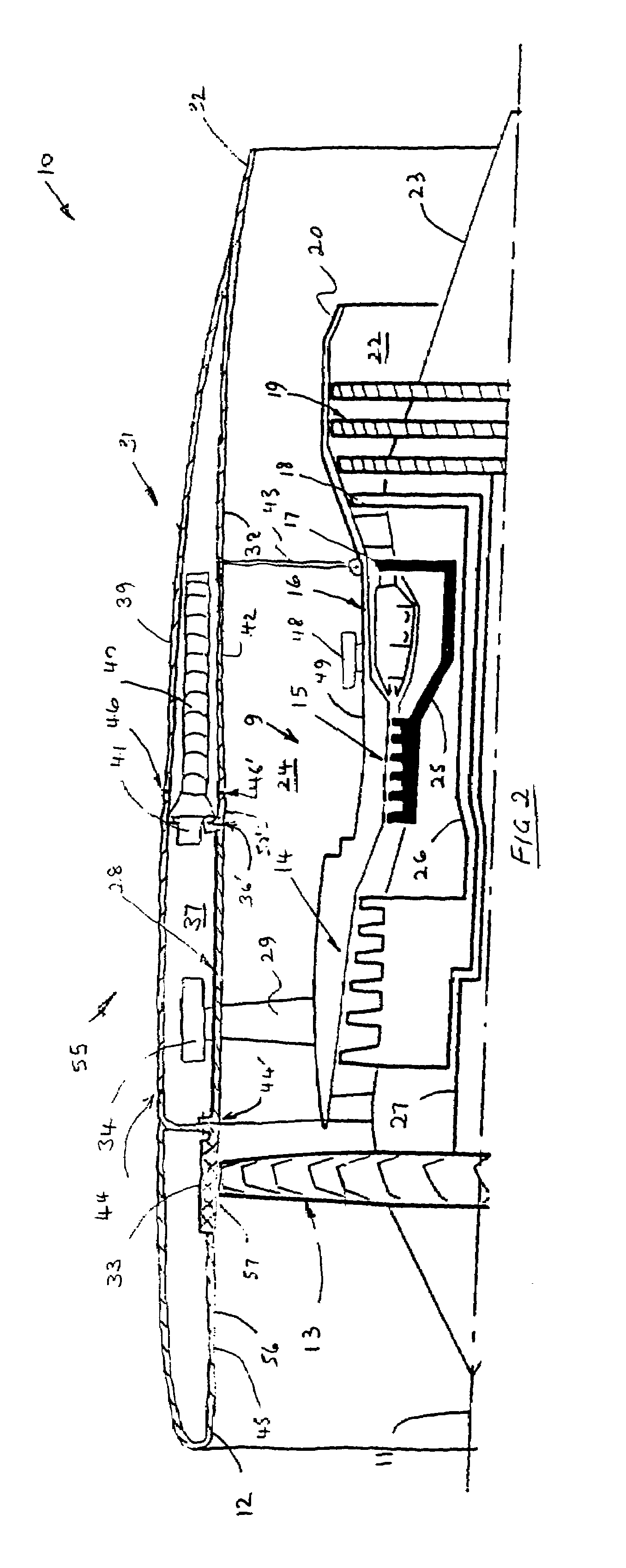
[0004]Therefore it is an object of the present invention to provide a nacelle arrangement that reduces the number of openable doors, reduces weight of the assembly and reduces aerodynamic drag. These are accomplished by reducing the number of nacelle components to two, with primarily the fan cowl doors being integrated partially into the intake and substantially into the thrust reverser unit. This arrangement also integrates the fan containment system into the nacelle intake removing the need for a bolted flange joint and reducing the size of the fan casing chamber fire zone. As the fan case accessory fire zone is reduced in size less fire extinguishing equipment, ventilation requirements and fire protection treatment is required.
[0005]The reduced number of steps or gaps between nacelle components, especially in the external nacelle surface reduces aerodynamic drag. Access to the fan case mounted accessories and core engine is simplified by provision of a single power opening system and hold open rods to the extended thrust reverser unit. The intake of the present invention extends further rearwards and provides an extended length for natural airflow and subsequent aerodynamic drag reduction. By integrating the fan containment casing into the intake, there is no bolted flanged joint forward of the fan system enabling provision for improved acoustic panels thus reducing engine-generated noise.
[0008]Preferably, an acoustic panel extends between a downstream edge of the fan containment casing and a leading edge of the intake, thus reducing engine-generated noise.

Problems solved by technology

This conventional arrangement is disadvantaged in that there are two independent power opening system and hold-open rods for the fan cowl doors and thrust reverser doors.
Furthermore, the prior art nacelle comprises a joint between each section which leads to an undesirable disturbance in airflow over the nacelle inner and outer surfaces with resultant aerodynamic drag losses.
Thus the conventional arrangement is heavy and costly to manufacture and is disadvantaged by requiring two sets of doors to be opened for access to the engine.

Method used


Image

  • Aeroengine nacelle
  • Aeroengine nacelle
  • Aeroengine nacelle

Examples


Embodiment Construction

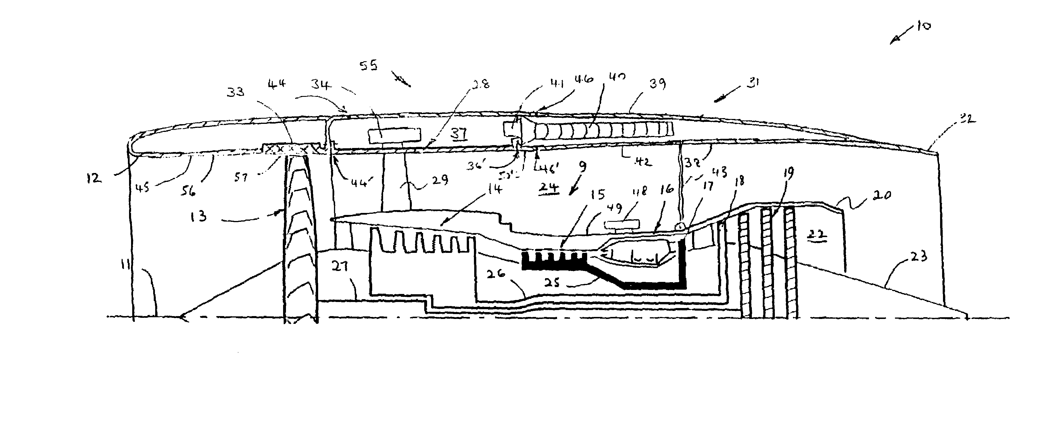
[0016]With reference to FIGS. 1 and 2, a ducted fan gas turbine engine generally indicated at 10 has a principal and rotational axis 11. The engine 10 comprises, in axial flow series, an air intake 12, a propulsive fan 13, an intermediate pressure compressor 14, a high-pressure compressor 15, combustion equipment 16, a high-pressure turbine 17, and intermediate pressure turbine 18, a low-pressure turbine 19 and a core nozzle 20. A core duct 22 is partly defined radially inwardly by a core plug 23 and radially outwardly by the core nozzle 20.

[0017]The gas turbine engine 10 works in the conventional manner so that air entering the intake 11 is accelerated by the fan 13 to produce two air flows: a first air flow into the intermediate pressure compressor 14 and a second air flow which passes through a bypass duct 24 to provide propulsive thrust. The intermediate pressure compressor 14 compresses the air flow directed into it before delivering that air to the high pressure compressor 15 ...


PUM


Abstract

A nacelle (55) for a gas turbine engine (10), the engine (10) comprising accessories (34) mounted to a fan casing (28) and a core engine (9), the nacelle (55) substantially surrounds the engine (10) and comprises an intake (12) and a thrust reverser unit (31). The thrust reverser unit (31) is formed by two generally C-shaped portions (31a, 31b). The thrust reverser unit (31) is openable to provide access to the accessories (34) and the core engine (9). The nacelle (55) further comprises a fan containment casing (33) that is integral with the intake (12).

Description

FIELD OF THE INVENTION[0001]The present invention relates to a nacelle for a gas turbine engine and in particular a nacelle configuration comprising an openable thrust reverser unit to provide improved access to accessories mounted on a fan casing and a core engine.BACKGROUND OF THE INVENTION[0002]A conventional nacelle for a turbofan gas turbine engine comprises three major components: an intake, fan cowl doors and a thrust reverser unit. These turbofan engines also incorporate a fan containment system attached to an engine fan casing. The fan cowl doors are generally C-shaped that are each opened by a power opening system and hold-open rods for access to fan casing mounted accessories. The thrust reverser unit also comprises two generally C-shaped doors that are each opened by a further power opening system and hold-open rods for access to the core engine and other core mounted engine accessories.[0003]This conventional arrangement is disadvantaged in that there are two independen...

Claims


Application Information

Patent Timeline
IPC IPC(8): B64B1/28B64D29/00B64D29/08F01D5/00F01D25/00F02C7/00F02C7/32F02K1/64
CPCB64D29/08F01D5/005F01D25/002F02C7/00F02K1/64F02C7/32F05D2230/80Y02T50/671Y02T50/673Y02T50/60
Inventor JONES, EMLYNSTRETTON, RICHARD G
Owner ROLLS ROYCE PLC
Learn More