Wind power installation with separate primary and secondary cooling circuits

a cooling circuit and wind power technology, applied in the direction of magnetic circuit rotating parts, electric generator control, magnetic circuit shape/form/construction, etc., can solve the problems of air with high salt content being aspirated, heat loss, pressure drop, etc., and achieve low cost and maintenance free

Inactive Publication Date: 2006-06-06
SIEMENS AG
View PDF17 Cites 96 Cited by
  • Summary
  • Abstract
  • Description
  • Claims
  • Application Information

AI Technical Summary

Benefits of technology

[0014]According to another feature of the present invention, the secondary air cooler may be constructed in the form of a heat exchanger which is designed as tube bundle and secured to the nacelle or forming part of the nacelle. Suitably, the tube bundle is disposed in an upper portion about the nacelle. Heated air produced by the generator or other electrical components connected to the primary cooling circuit rises or is forced by fans into the interstices between the tube bundles and cooled there by wind flowing through the tube bundles. The cooled air of the primary cooling circuit is flowed back through natural convection or by a further fan for cooling the generator or other electrical components disposed in the nacelle. The arrangement of the tube bundle on the nacelle ensures an alignment of the tubes of the tube bundle in parallel relationship to a wind direction so as to provide a sufficient cooling action by wind velocities and sufficient passage of air through the tube bundle. The tube bundle forms the heat exchanger between the primary and secondary circuits.
[0016]According to another feature of the present invention, the secondary cooler has an inlet and an outlet, wherein the inlet or the outlet of the secondary cooler is disposed on the nacelle at a location which has enhanced flow dynamics.
[0018]Compared with facilities operating with air-water cooling systems, a wind power installation according to the present invention has the advantage of being compact, substantially maintenance-free and reliable operation, without any need for preparing coolants in great amounts. As a result, costs are low. Compared to wind power plants with closed circulating ventilation in particular of the generators, a wind power installation according to the present invention is less likely to breakdown as a result of humid or salty air.
[0019]The outgoing heated air of the primary cooling circuit can be used to heat the nacelle, rotor blades, in particular during the cold season. Condensate formations on electrical equipment and ice build up on the rotor blades are thereby eliminated.

Problems solved by technology

The conversion of energy normally results in energy loss in the form of heat.
This is disadvantageous especially when the outside air is humid or has a high salt content particularly in coastal regions, and the components to be cooled are then exposed to this humid and salty air.
This low pressure results in a pressure drop between each mouth of a rotor blade and an opening on a rotor blade distal side of the nacelle.
The provision of such a closed circulating ventilation is disadvantageous and, especially when located off-shore, results air with high salt content being aspirated.
Moreover, noise is generated by the mouths at the rotor blades.
It is hereby disadvantageous that the tower cross section is already formed with channels.
Moreover, also a closed circulating ventilation system is involved here which is susceptible to penetration of dirt and humidity and thus is unsuitable for carrying out a reliable operation.
This cooling system is however able to dissipate only little heat energy.

Method used


Image

  • Wind power installation with separate primary and secondary cooling circuits
  • Wind power installation with separate primary and secondary cooling circuits
  • Wind power installation with separate primary and secondary cooling circuits

Examples


Embodiment Construction

[0027]Throughout all the Figures, same or corresponding elements are generally indicated by same reference numerals. These depicted embodiments are to be understood as illustrative of the invention and not as limiting in any way. It should also be understood that the drawings are not necessarily to scale and that the embodiments are sometimes illustrated by graphic symbols, phantom lines, diagrammatic representations and fragmentary views. In certain instances, details which are not necessary for an understanding of the present invention or which render other details difficult to perceive may have been omitted.

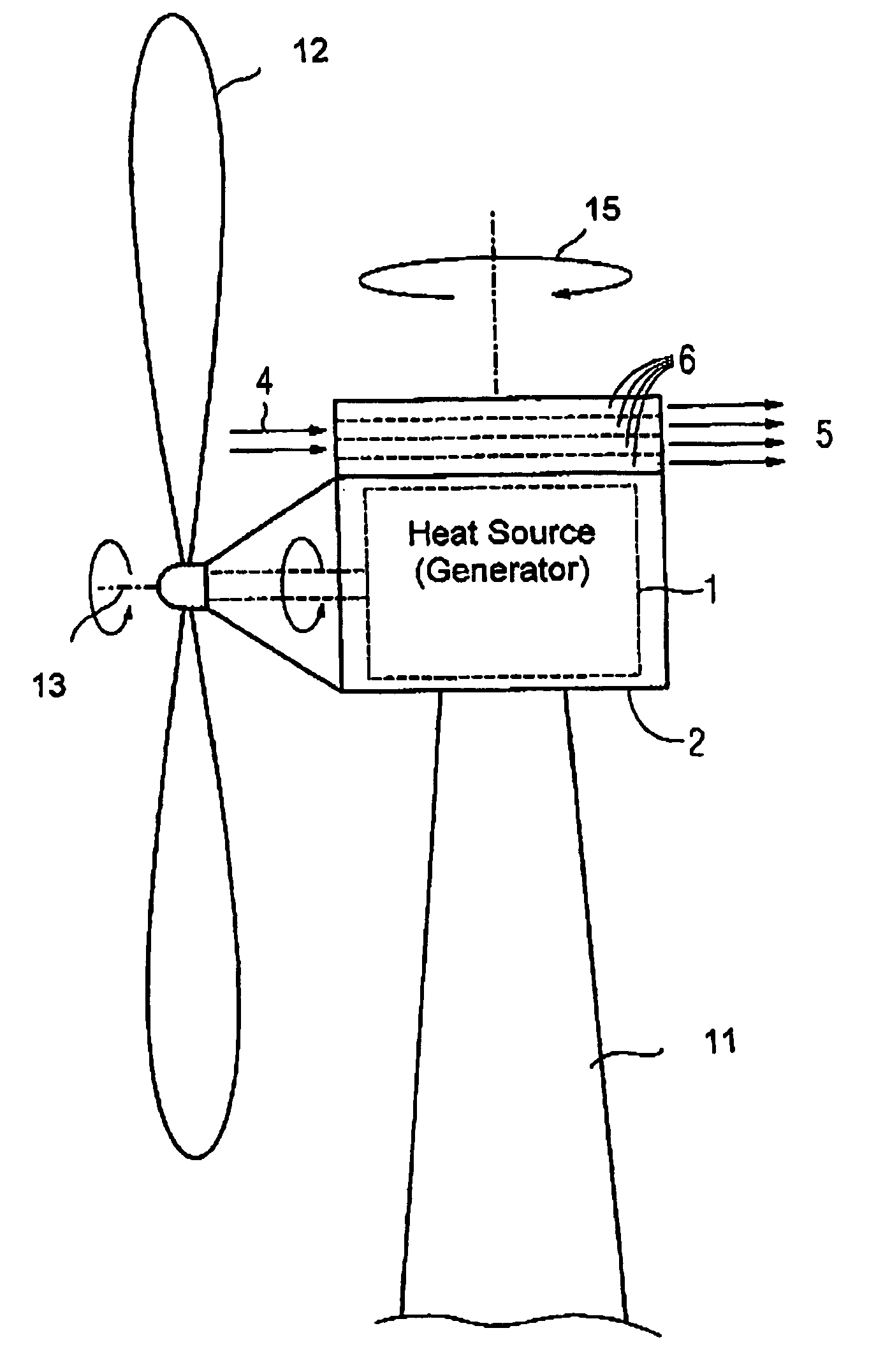
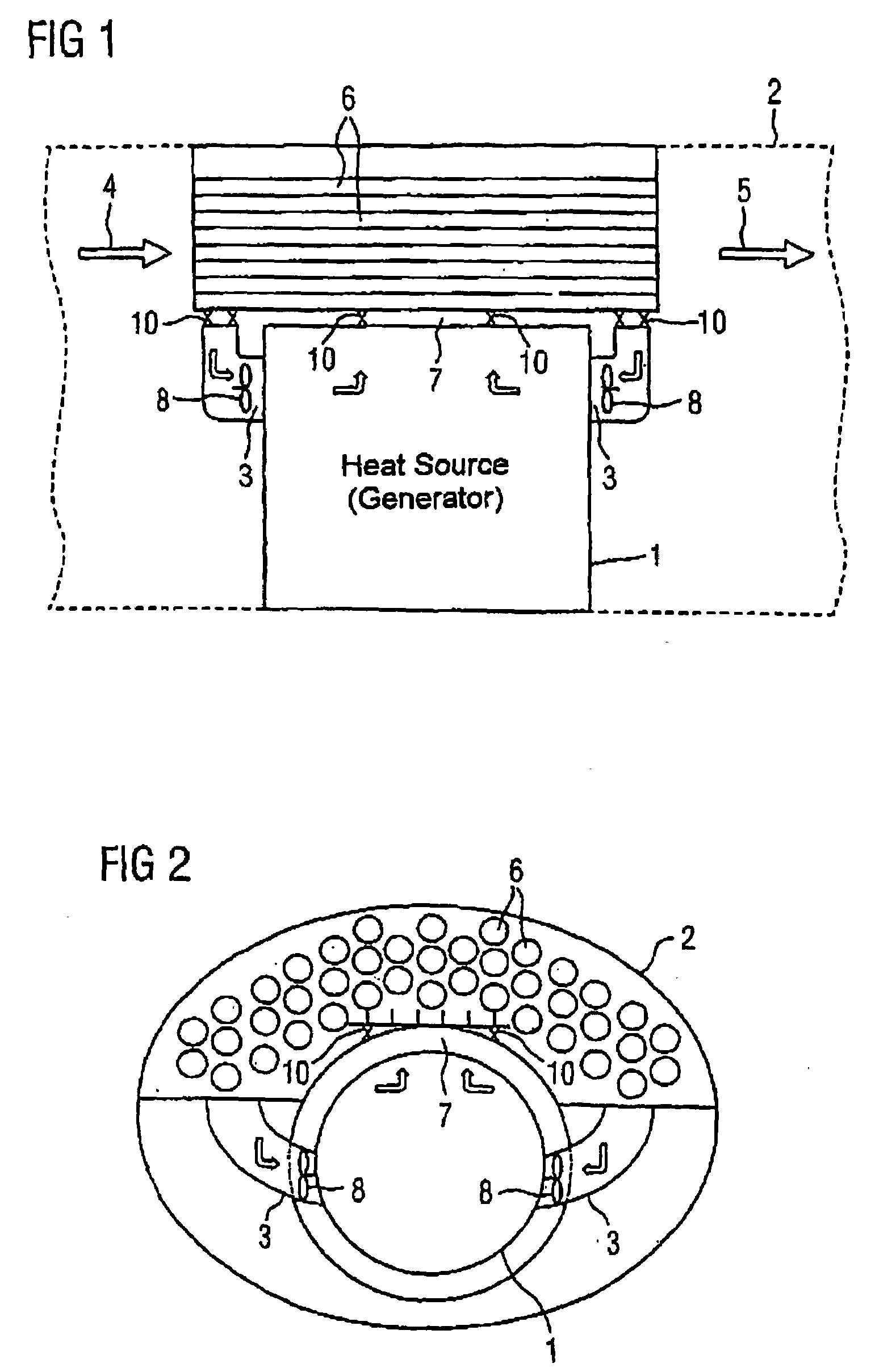
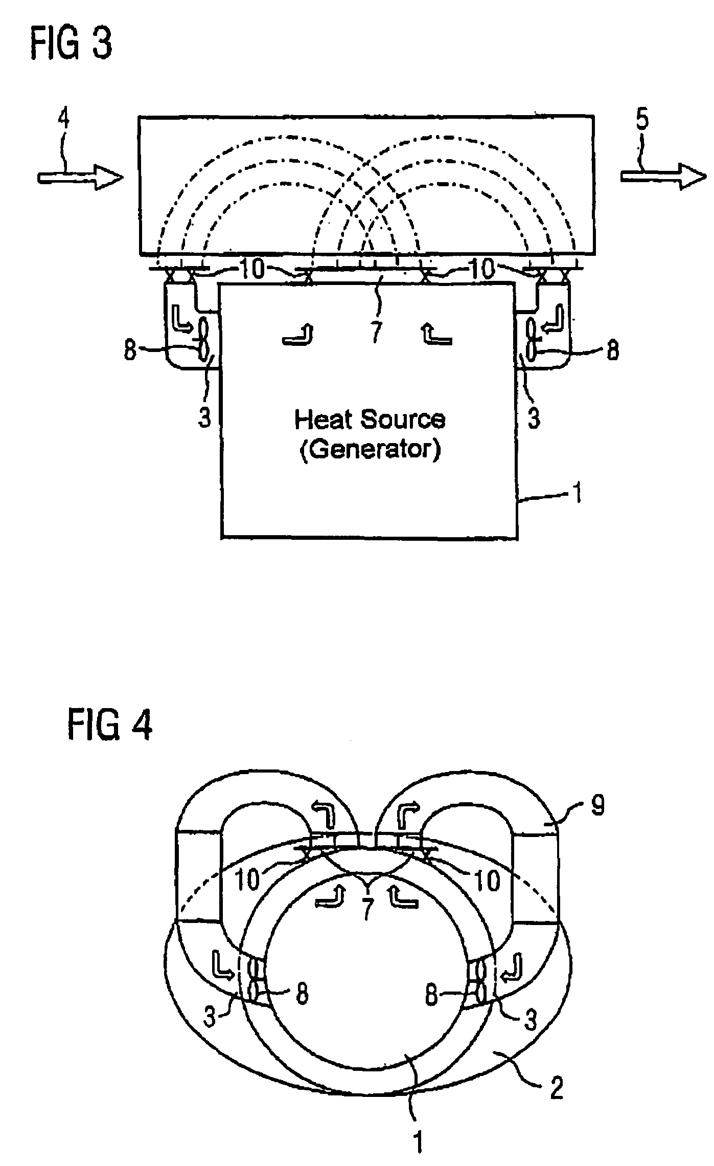
[0028]Turning now to the drawing, and in particular to FIG. 1, there is shown a longitudinal section of one embodiment of a wind power installation according to the present invention, including a nacelle 2 which is supported by tower 11 (FIG. 5). The nacelle 2 supports at least one rotor blade 12 which is rotatable around a horizontal axis 13 by wind velocity to drive a genera...


PUM


Abstract

A wind power installation includes a nacelle for housing a generator, and a turbine having at least one rotor blade. At least the generator includes a closed primary cooing system, and the nacelle is provided with a cooling system for cooling the primary cooling system in dependence on an output of the generator or generator losses.

Description

CROSS-REFERENCES TO RELATED APPLICATIONS[0001]This application is a continuation of prior filed copending PCT International application no. PCT / DE2003 / 002355, filed Jul. 11, 2003, which designated the United States and on which priority is claimed under 35 U.S.C. §120, and which claims the priority of German Patent Application, Serial No. 102 33 947.3, filed Jul. 25, 2002, pursuant to 35 U.S.C. 119(a)–(d).BACKGROUND OF THE INVENTION[0002]The present invention relates, in general, to a wind power plant, and more particularly to a wind power installation of a type having a generator disposed in a nacelle and including a cooling circuit, and a turbine with at least one rotor blade.[0003]Nothing in the following discussion of the state of the art is to be construed as an admission of prior art.[0004]Typically, a wind power plant has a rotor blade which is rotatable around a horizontal axis and pivotable around a vertical axis to turn the rotor blade in appropriate alignment to the wind....

Claims


Application Information

Patent Timeline
Patent Type & Authority Patents(United States)
IPC IPC(8): F03D11/00H02K9/00A47G9/10H02K7/18H02K9/04H02K9/10
CPCF03D9/002F03D11/00F03D11/0025H02K9/12H02K7/1823F05B2260/20H02K7/1838H02K7/183Y02E10/722Y02E10/725F03D80/40F03D9/25F03D80/60Y02E10/72
Inventor KRUGER-GOTZMANN, MANFREDSCHILLER, CHRISTIANZWARG, GUNTER
Owner SIEMENS AG
Why Eureka
Try Eureka