Water-cooled control device for a plastics processing machine

a control device and plastic processing technology, applied in the field of control devices, can solve the problems of difficult to reconcile with aforementioned codes, installation of fans in the housing wall, and the housing to the outside, and achieve the effects of convenient operation, reliable heat dissipation, and sufficient cooling action

Inactive Publication Date: 2007-06-14
KRAUSS MAFFEI KUMSTSTOFFTECHNIK GMBH
View PDF34 Cites 7 Cited by
  • Summary
  • Abstract
  • Description
  • Claims
  • Application Information

AI Technical Summary

Benefits of technology

[0008] A control device according to the invention, e.g. for use in an injection molding machine, provides reliable dissipation of heat generated by electronic control components inside a housing, independent of the ambient temperature and in compliance with protective housing codes for control systems of injection molding machines. The separation of pump and cooler enables a disposition of the cooler outside the housing of the control system, without requiring the pump to be moved outside. Furthermore, it is not necessarily required to arrange the at least one cooling element (cooling plate) upon a component of the control system. Although such a configuration may be desired, the fact remains that the cooling element can be placed anywhere inside the housing. Optionally, one or more additional cooling plates may be provided inside the housing for placement upon the components of the cooling system and connected to the coolant circuit.
[0009] The use of a cooler with fan allows also to achieve a greater cooling capacity so as to ensure sufficient cooling action even when the difference between the internal and external temperatures is small.

Problems solved by technology

Installation of fans in the housing wall for conducting heat from inside the housing to the outside is however difficult to reconcile with a compliance of the aforementioned codes.

Method used


Image

  • Water-cooled control device for a plastics processing machine
  • Water-cooled control device for a plastics processing machine
  • Water-cooled control device for a plastics processing machine

Examples


Embodiment Construction

[0018] Throughout all the Figures, same or corresponding elements are generally indicated by same reference numerals. These depicted embodiments are to be understood as illustrative of the invention and not as limiting in any way. It should also be understood that the drawings are not necessarily to scale and that the embodiments are sometimes illustrated by graphic symbols, phantom lines, diagrammatic representations and fragmentary views. In certain instances, details which are not necessary for an understanding of the present invention or which render other details difficult to perceive may have been omitted.

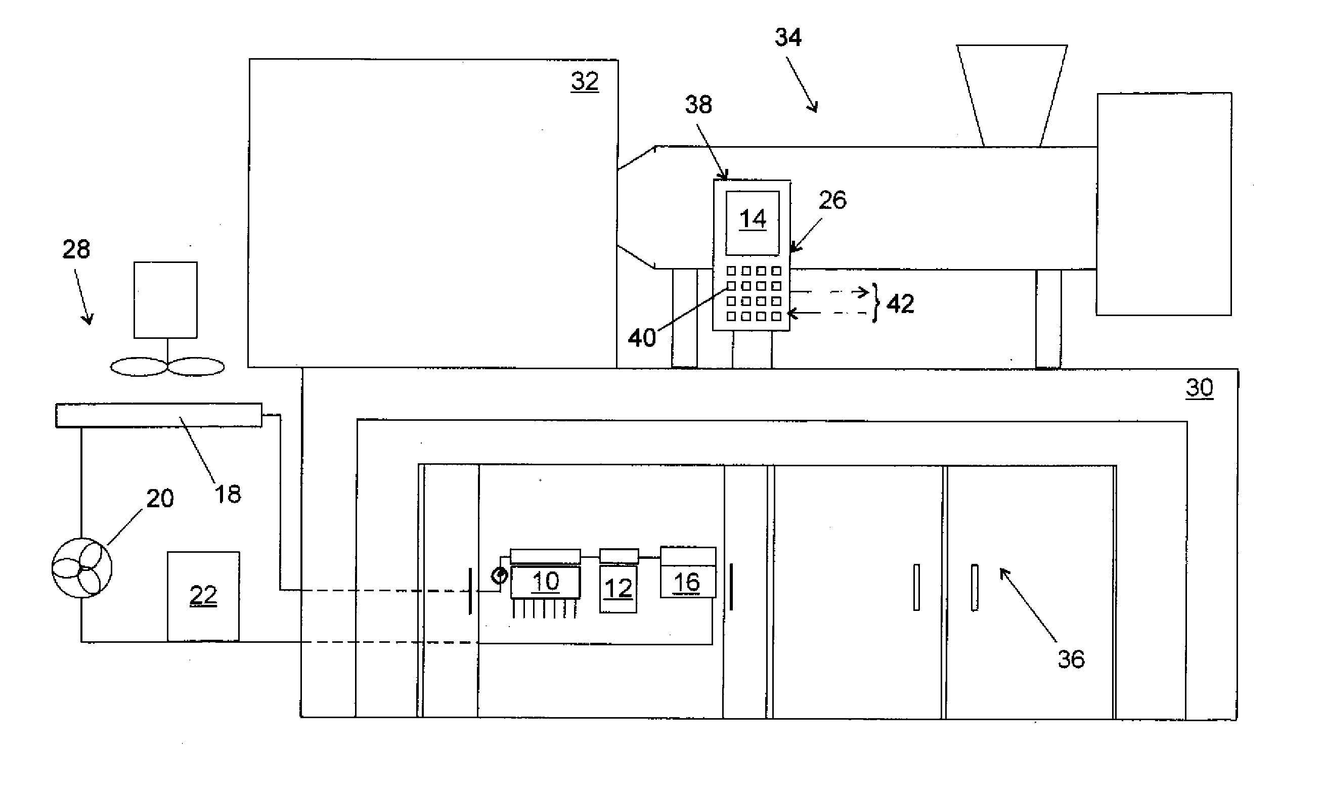
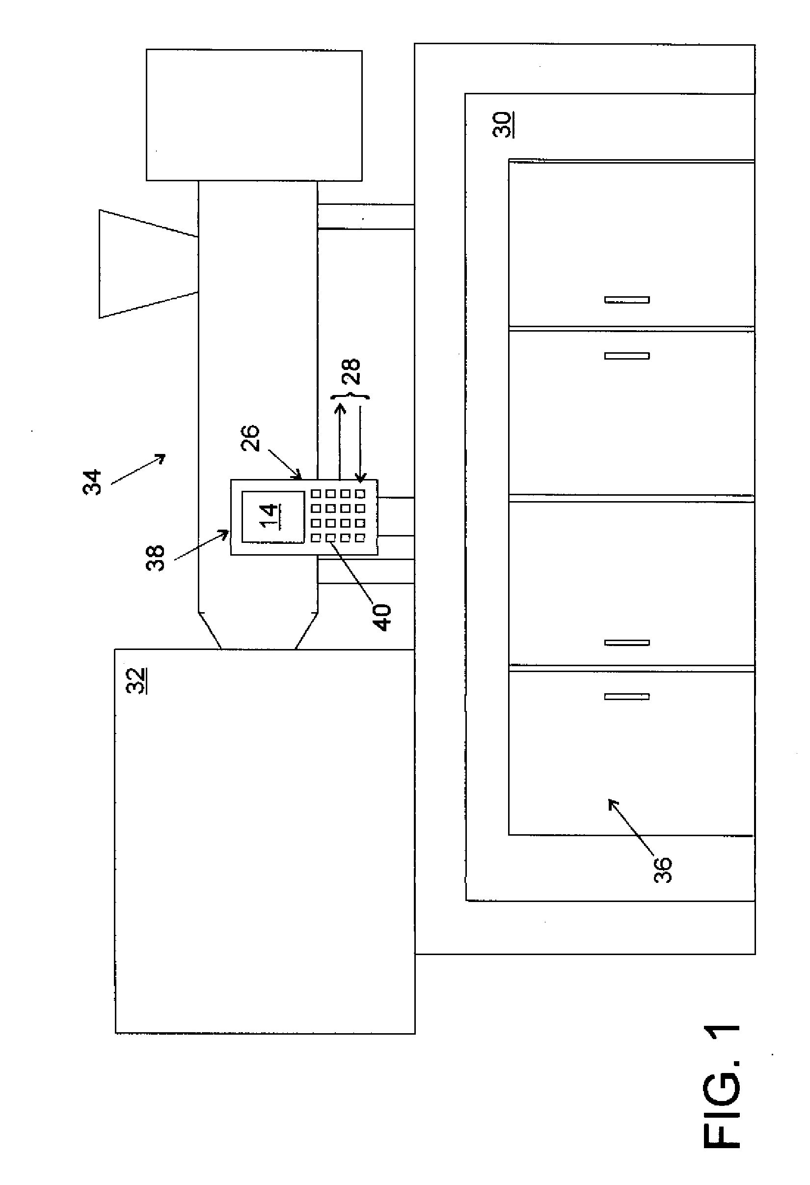
[0019] Turning now to the drawing, and in particular to FIG. 1, there is shown, by way of example of a plastics processing machine, an injection molding machine having a machine bed 30 for support of a clamping unit 32 and a plasticizing and injection unit 34. A switch cabinet 36 is located below the machine bed 30 for accommodating electrical, electronic and / or electromecha...


PUM

PropertyMeasurementUnit
heataaaaaaaaaa
temperatureaaaaaaaaaa
temperaturesaaaaaaaaaa

Abstract

A control device for use with a plastics processing machine, e.g. an injection molding machine, includes a housing which is constructed for protection against ingress of water in compliance with the IP code and accommodates a heat source such as a CPU unit or a display unit. A cooling system is provided for dissipating heat generated by the heat source and includes a pump for pumping a coolant, at least one cooling element arranged inside the housing, a cooler provided outside the housing, and a coolant circuit for circulation of the coolant. The coolant circuit fluidly connects hereby the pump, the cooling element and the cooler with one another.

Description

CROSS-REFERENCES TO RELATED APPLICATIONS [0001] This application is a continuation of prior filed copending PCT International application no. PCT / EP2004 / 003572, filed Apr. 3, 2004, which designated the United States and on which priority is claimed under 35 U.S.C. §120. BACKGROUND OF THE INVENTION [0002] The present invention relates, in general, to a control device, in particular for application in a plastics processing machine, such as an injection molding machine or extruder. [0003] Nothing in the following discussion of the state of the art is to be construed as an admission of prior art. [0004] A control device for a machine tool or a plastics processing machine, such as an injection molding machine for producing a plastic article, generally includes a CPU unit, a power supply for voltage regulation and a display unit for visualizing operating data of the injection molding machine. For protection from damaging environmental influences, these components of the control device are...

Claims


Application Information

Patent Timeline
Patent Type & Authority Applications(United States)
IPC IPC(8): B29C45/00B29C35/16B29C45/72H02B1/28H02B1/56
CPCB29C35/16B29C45/72H02B1/28H02B1/56
Inventor GRIMM, GUNTHER
Owner KRAUSS MAFFEI KUMSTSTOFFTECHNIK GMBH
Why Eureka
Try Eureka