Reflector deflection device

A technology of mirrors and mirror bases, applied in the field of mirrors, can solve the problems of the degradation of the imaging quality of the optical system and the influence of the satellite operation attitude.

Inactive Publication Date: 2019-09-10
CHANGCHUN INST OF OPTICS FINE MECHANICS & PHYSICS CHINESE ACAD OF SCI
View PDF3 Cites 3 Cited by
  • Summary
  • Abstract
  • Description
  • Claims
  • Application Information

AI Technical Summary

Problems solved by technology

In applications such as aerospace, these harmful vibrations will lead to a decrease in the imaging quality of the optical system, and seriously affect the operating attitude of the satellite

Method used


Image

  • Reflector deflection device
  • Reflector deflection device
  • Reflector deflection device

Examples


Embodiment Construction

[0015] The technical solutions in the embodiments of the present invention will be clearly and completely described below in conjunction with the accompanying drawings in the embodiments of the present invention. Obviously, the described embodiments are only part of the embodiments of the present invention, not all of them. Based on the implementation manners in the present invention, all other implementation manners obtained by persons of ordinary skill in the art without making creative efforts belong to the scope of protection of the present invention.

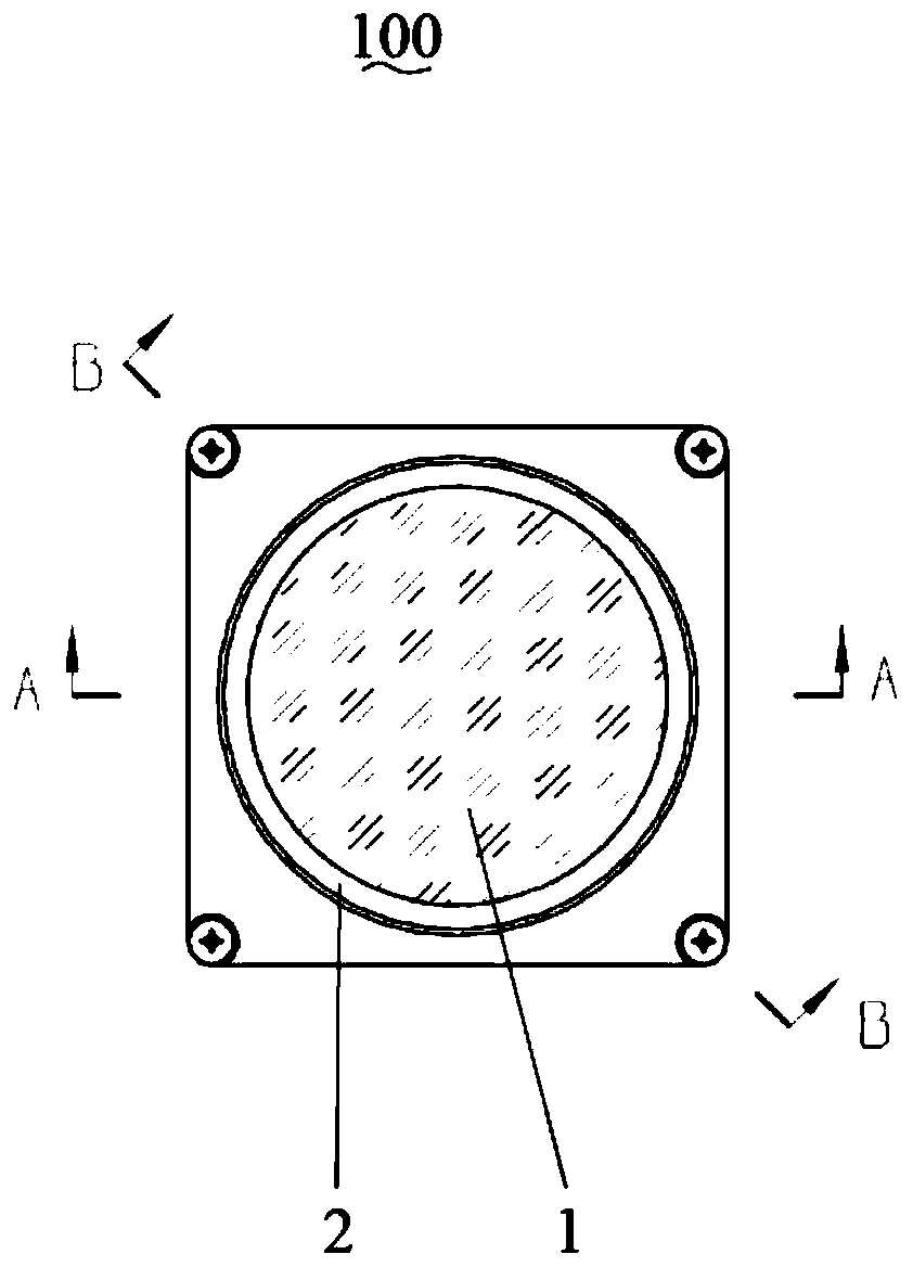
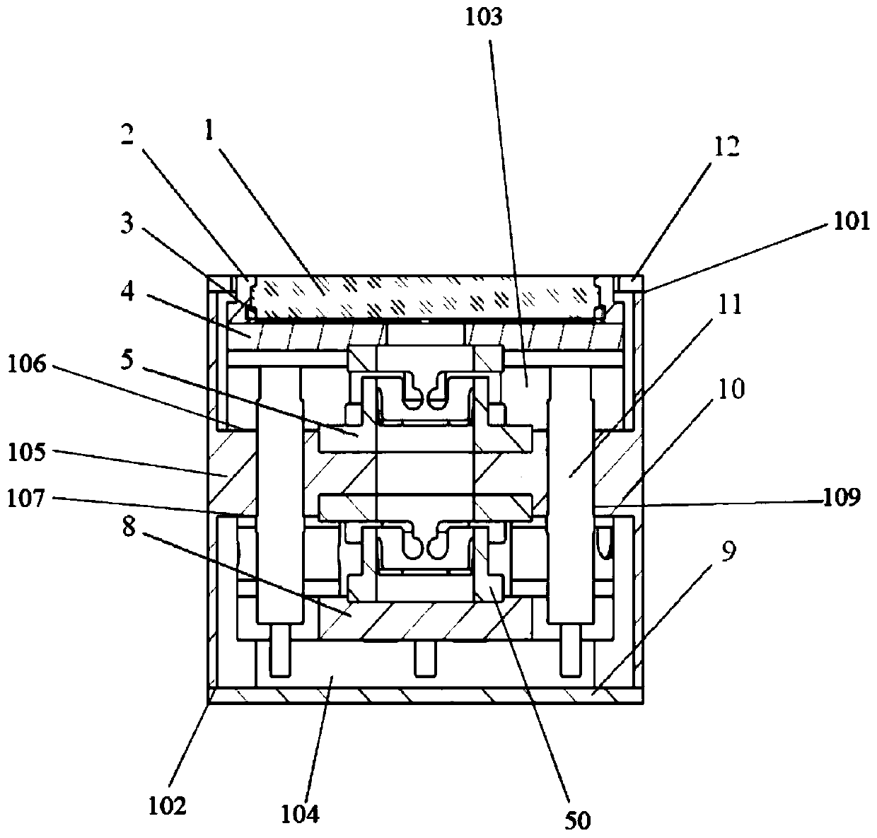
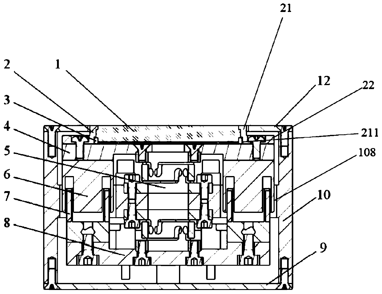
[0016] Please refer to Figure 1 to Figure 3 , a deflecting mirror device 100 provided in a preferred embodiment of the present invention includes a mirror 1, a mirror base 2, a substrate 4, a first elastic element 5, a second elastic element 50, a first magnetic member 6, and a second magnetic element 7. Compensation plate 8, base 10 and displacement sensor 11; said mirror 1 is fixed in said mirror base 2, said mirror base...


PUM


Abstract

The invention discloses a reflector deflection device. The device comprises a reflector, a reflector base, a substrate, a first elastic element, a second elastic element, a first magnetic element, a second magnetic element, a compensation plate, a base and a displacement sensor; the reflector base is arranged at one side of the substrate, the first elastic element and the first magnetic element are arranged at one side, opposite to the reflector base, of the substrate; one side, opposite to the reflector base, of the substrate is arranged at one end of the base through the first elastic element; the compensation plate is arranged at the other end of the base through the second elastic element, the second magnetic element is arranged at the same side of the substrate and the second elasticelement, and a magnetic field can be produced between the second magnetic element and the first magnetic element so that the first magnetic element and the second magnetic element can mutually slide and cooperate; and the displacement sensor is arranged on the base. When the reflector and the substrate perform deflection movement under the driving force of the first magnetic element, the compensation plate can perform deflection movement towards an opposite direction in the same frequency and amplitude under the driving of the counterforce of the second magnetic element, thereby counteractingthe counterforce of the deflection of the reflector.

Description

technical field [0001] The invention relates to the technical field of mirrors, in particular to a deflection mirror device. Background technique [0002] As a component for fast and precise control of beam pointing, fast deflecting mirror devices are increasingly used in aviation, aerospace, and industrial fields. The functions of fast deflecting mirror devices in optical systems mainly include visual axis stabilization and image motion compensation. However, during the use of the fast deflecting mirror device, while the mirror is oscillating at high frequency, its supporting structure will also be subjected to a corresponding reaction force, so that the corresponding vibration torque is transmitted to the installation carrier of the fast deflecting mirror device. In applications such as aerospace, these harmful vibrations will lead to a decrease in the imaging quality of the optical system, and seriously affect the operating attitude of the satellite. Contents of the inv...

Claims


Application Information

Patent Timeline
Patent Type & Authority Applications(China)
IPC IPC(8): G02B26/08
CPCG02B26/0816
Inventor 徐宁
Owner CHANGCHUN INST OF OPTICS FINE MECHANICS & PHYSICS CHINESE ACAD OF SCI
Why Eureka
Try Eureka