
Reflective plane of reflective array antenna

A reflective array antenna and reflective surface technology, used in antennas, antenna arrays, electrical components, etc., to reduce maintenance costs, reduce warpage, and reduce product defect rates

Active Publication Date: 2014-04-16
KUANG CHI INNOVATIVE TECH +1
View PDF6 Cites 0 Cited by
  • Summary
  • Abstract
  • Description
  • Claims
  • Application Information

AI Technical Summary

Problems solved by technology

[0003] The technical problem to be solved by the present invention is to provide a reflective surface of the reflectarray antenna that can improve the warping problem in view of the defect that the reflective surface of the reflectarray antenna in the prior art is prone to warping

Method used


Image

  • Reflective plane of reflective array antenna
  • Reflective plane of reflective array antenna
  • Reflective plane of reflective array antenna

Examples


Embodiment Construction

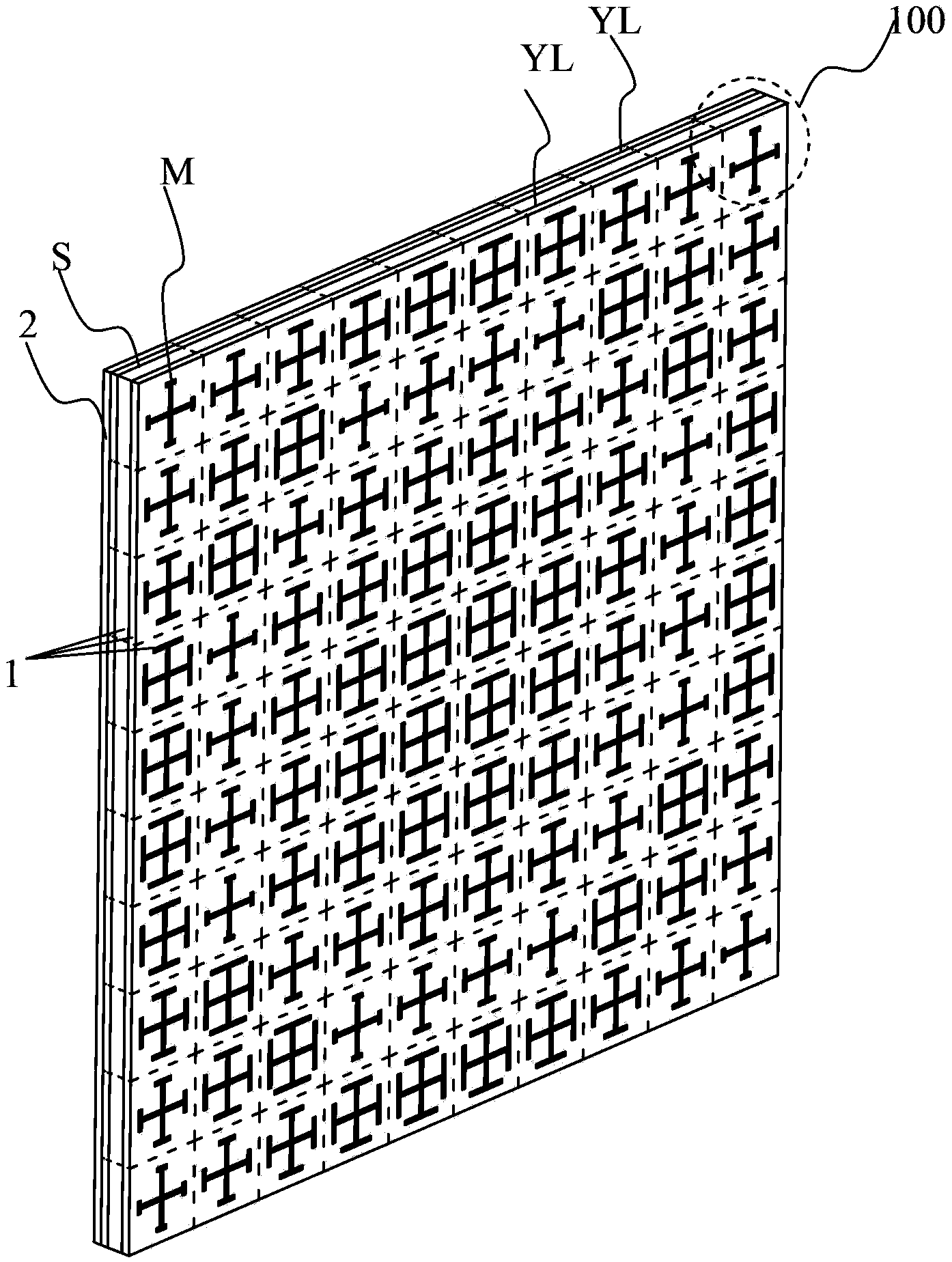
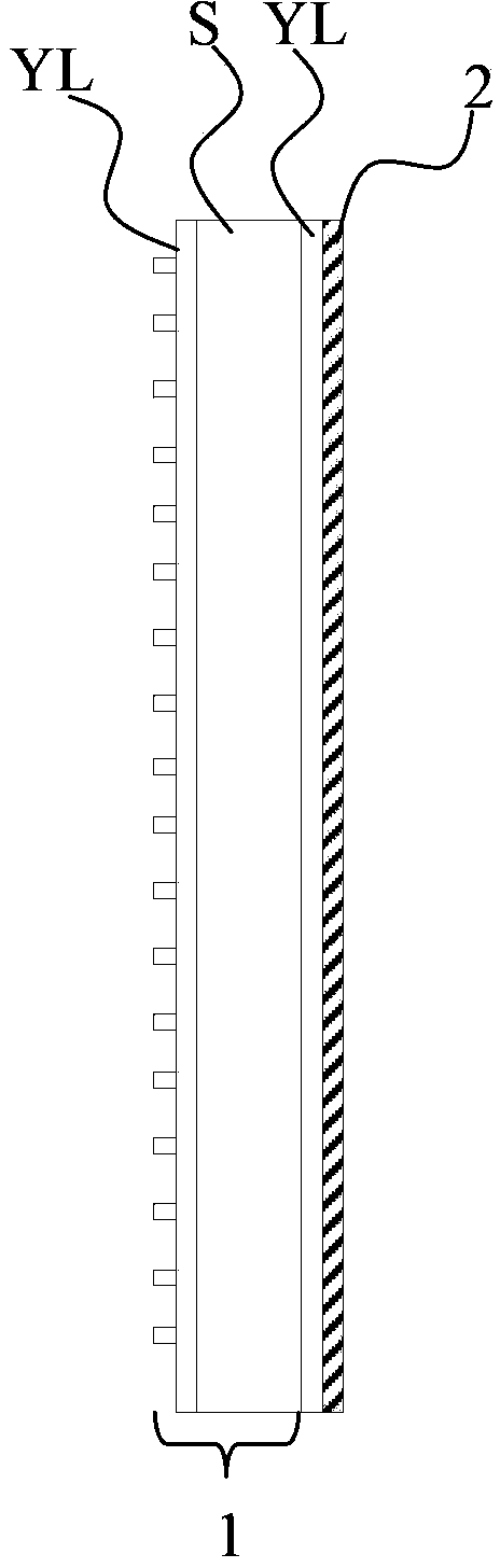
[0085] The reflective surface of the reflectarray antenna includes a substrate, an artificial structure layer disposed on one side of the substrate that has an electromagnetic response to electromagnetic waves, and a reflective layer disposed on the other side of the substrate for reflecting electromagnetic waves, between the substrate and the artificial structure layer and / or At least one stress buffer layer is arranged between the substrate and the reflective layer.

[0086] figure 1 and image 3 They are respectively a three-dimensional structural schematic diagram and a cross-sectional view of a preferred embodiment of the reflective surface of the reflectarray antenna of the present invention. As a preferred example, the reflective surface of the reflectarray antenna includes a substrate S, an artificial structure layer disposed on one side of the substrate S that has an electromagnetic response to electromagnetic waves, and a reflective layer 2 disposed on the other sid...


PUM


Abstract

The invention provides a reflector of a reflective array antenna comprising a base board, an artificial structure layer which is arranged on one side of the base board and has electromagnetic response to electromagnetic wave and a reflecting layer which is arranged on the other side of the base board and is used for reflecting the electromagnetic wave. The invention is characterized in that at least one stress buffer layer is arranged between the base board and the artificial structure layer and / or between the base board and the reflecting layer, wherein the stretching strength of the stress buffer layer is less than that of the base board, a breakage elongation of the stress buffer layer is larger than that of the artificial structure layer and the reflecting layer. Due to the fact that the stress buffer layer is arranged between the base board and the artificial structure layer and / or between the base board and the reflecting layer, change of surface evenness caused by different coefficients of thermal expansion among different materials can be improved by the stress buffer layer, and the reflecting layer and / or the artificial structure is enabled to be placed on a smooth flat surface. So that the warping condition is reduced, and reject ratio and maintenance cost of products are reduced.

Description

technical field [0001] The invention relates to the field of reflectarray antennas, more specifically, to a reflective surface of a reflectarray antenna capable of buffering stress. Background technique [0002] Reflectarray antennas are widely used in long-distance wireless transmission systems such as satellite communications and deep space exploration because of their low profile, low cost, easy conformality, easy integration, easy portability, and good concealment. A reflectarray antenna generally includes a dielectric plate, a plurality of unit structures disposed on the dielectric plate, and a reflective layer disposed on the other side of the dielectric plate. In the existing reflectarray antenna, the reflective layer or a plurality of unit structures are attached to both sides of the dielectric board by copper-clad etching or hot-pressed. The reflectarray antenna prepared by the above method will have the following problems in application: the dielectric plate and t...

Claims


Application Information

Patent Timeline
Patent Type & Authority Patents(China)
IPC IPC(8): H01Q21/00H01Q15/00H01Q15/14H01Q19/00H01Q19/10
CPCH01Q3/46
Inventor 刘若鹏季春霖殷俊
Owner KUANG CHI INNOVATIVE TECH
Learn More