Permanent magnet synchronous motor anti-demagnetization control method

A technology of permanent magnet synchronous motor and control method, applied in the direction of electronic commutation motor control, control system, electrical components, etc., can solve the problems of high motor speed, hindering the popularization of new energy vehicles, and instantaneous peak current impact of motor windings. The effect of reducing rare earth content, reducing the risk of demagnetization, and reducing costs

Inactive Publication Date: 2013-03-20
UNITED AUTOMOTIVE ELECTRONICS SYST
View PDF3 Cites 7 Cited by
  • Summary
  • Abstract
  • Description
  • Claims
  • Application Information

AI Technical Summary

Problems solved by technology

[0006] The disadvantage of this method is that if the vehicle runs at high speed when a failure occurs, the motor speed will be relatively high
[0008] The disadvantage of this method is that: when the mode is switched, an instantaneous peak current impact will be generated in the motor winding, and the current amplitude may exceed 2 times the maximum phase current, which may cause demagnetization of the permanent magnet steel and decrease the performance of the motor
If the intrinsic coercive force of the permanent magnet steel is small, the magnet will demagnetize, and the performance of the motor will be greatly reduced; Under the situation of sharply rising rare earth prices, the total cost of motors will increase significantly, which will inevitably affect the prices of hybrid electric vehicles and pure electric vehicles, and seriously hinder the popularization of new energy vehicles.

Method used


Image

  • Permanent magnet synchronous motor anti-demagnetization control method
  • Permanent magnet synchronous motor anti-demagnetization control method
  • Permanent magnet synchronous motor anti-demagnetization control method

Examples


Embodiment Construction

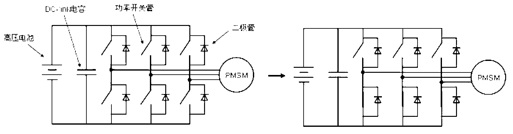
[0025] The control method for suppressing the demagnetization rate of the permanent magnet synchronous motor for new energy vehicles described in the present invention can reduce The instantaneous peak current generated by the original method prevents or reduces the risk of demagnetization of the permanent magnet steel of the motor. Therefore, in the design of the motor, the magnetic circuit design can be carried out based on the reduced instantaneous peak current, and the magnetic steel with a lower coercive force can be selected to reduce the content of rare earths and achieve the purpose of reducing costs.

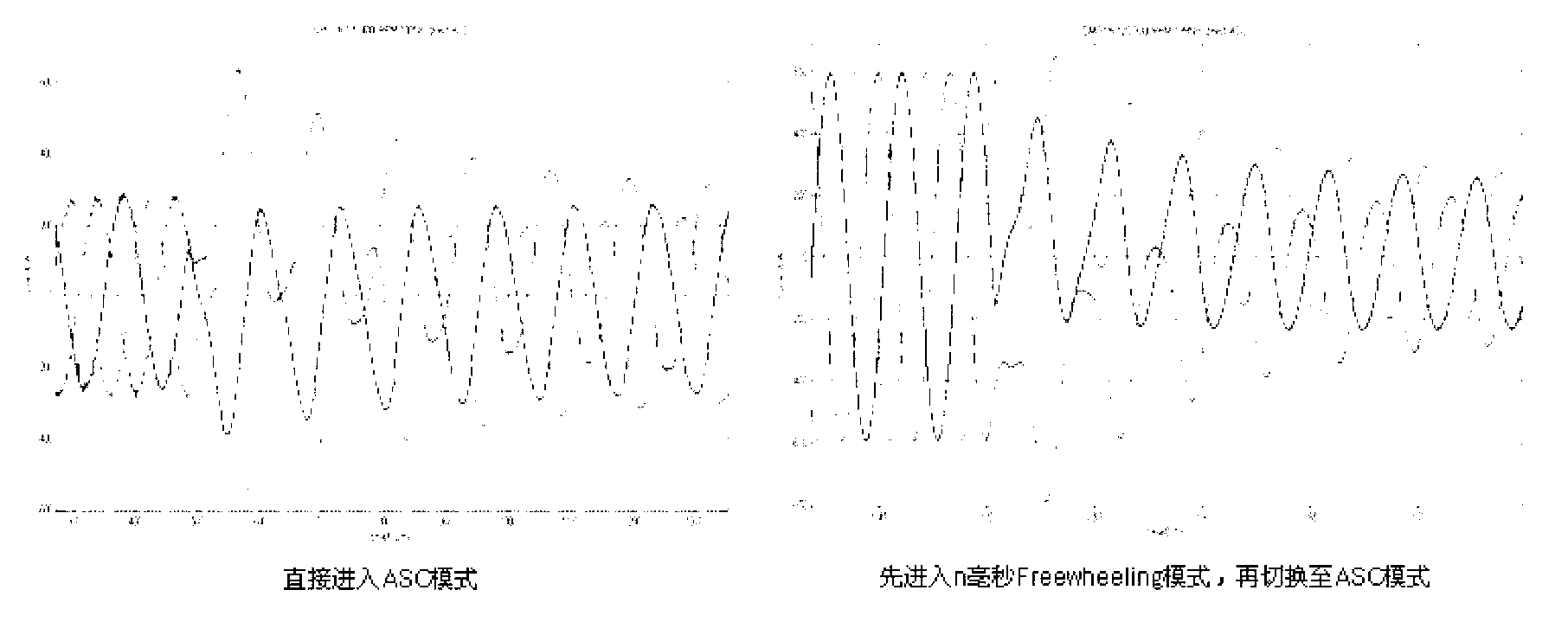
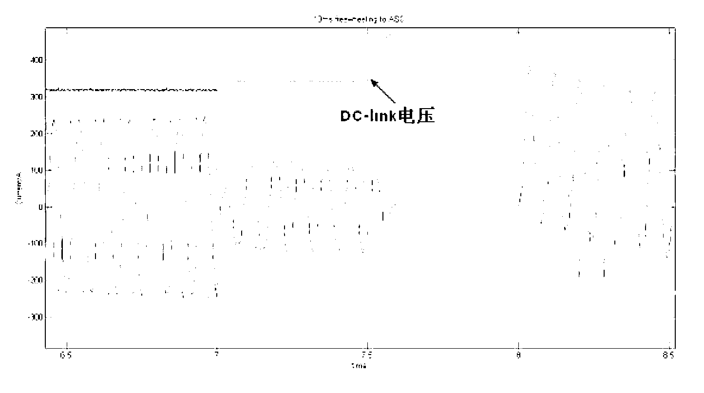
[0026] The control method described in the present invention is: if the motor is running in the low and medium speed range (less than TBD% of the maximum speed, the TBD value can be matched according to the actual application), the system fails, such as detecting that the motor phase current exceeds the threshold. At this time, the controller responds to the failure, fr...


PUM


Abstract

The invention discloses a permanent magnet synchronous motor anti-demagnetization control method which comprises the following steps: first, detecting motor speed and motor phase current, second, if the motor speed is less than the maximum speed of revolution of track before detect percent (TBD%), a system becomes invalid and detects the motor phase current to be over a threshold value, and a controller controls six switching tubes of a three phase permanent magnet synchronous motor to open, third, after n plurality of seconds, entering a next three insulated gate bipolar transistor (IGBT) short circuit module of the three phase permanent magnet synchronous motor, three switching tubes on the three phase permanent magnet synchronous motor keep opening, and the next three switching tubes of the three phase permanent magnet synchronous motor are controlled. According to the permanent magnet synchronous motor anti-demagnetization control method, when normal rotate speed operation of the motor is shifted into the next three IGBT short circuit pattern of the three phase permanent magnet synchronous, an instantaneous peak value large current produced according to an original method is reduced, and the risk of motor permanent magnet steel demagnetization is prevented or reduced. So when the motor is designed, magnetic circuit design can be carried out based on the reduced instantaneous peak value current, magnet steel with low coercivity is chosen, rare earth content is reduced, and the purpose of reducing cost is achieved.

Description

technical field [0001] The invention relates to a failure response control method for reducing the demagnetization rate of motor magnetic steel, and is especially suitable for permanent magnet synchronous motors used in new energy vehicles. Background technique [0002] In the design of permanent magnet synchronous motor (PMSM) for new energy vehicles, it is necessary to consider the risk of demagnetization of the permanent magnet steel in the motor under some harsh driving conditions. The higher the intrinsic coercivity (Hcj) of the magnet, the stronger the corresponding anti-demagnetization ability, but at the same time, due to the increase of the content of rare earth dysprosium in the magnet, the cost is correspondingly higher. [0003] The instantaneous peak current (Ipeak) that may occur in the motor under severe working conditions (such as mode switching) is one of the key factors affecting the demagnetization of the magnetic steel. [0004] When a failure occurs, th...

Claims


Application Information

Patent Timeline
Patent Type & Authority Applications(China)
IPC IPC(8): H02P6/00
Inventor 王萑徐鹏磊何海
Owner UNITED AUTOMOTIVE ELECTRONICS SYST
Why Eureka
Try Eureka