Device for corrugating a metal tube

A technology of metal pipes, equipment, applied in the field of equipment for making metal pipes into waves

Inactive Publication Date: 2013-03-27
NEXANS
View PDF5 Cites 0 Cited by
  • Summary
  • Abstract
  • Description
  • Claims
  • Application Information

AI Technical Summary

Problems solved by technology

The result is a radially adjusted bellows platen

Method used


Image

  • Device for corrugating a metal tube
  • Device for corrugating a metal tube
  • Device for corrugating a metal tube

Examples


Embodiment Construction

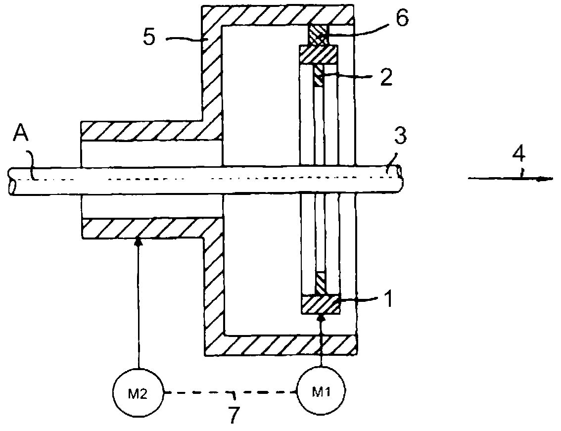
[0016] figure 1 A ring-shaped corrugator 1 is shown, which is rotatable about its axis and is driven for this purpose by a first electric motor M1 (hereinafter referred to as "motor M1"). A likewise ring-shaped bellows plate 2 protruding radially inwards from the bellows head 1 is accommodated in the bellows head 1 , preferably made of stainless steel. The corrugation platen can be adjusted radially within the corrugation head 1 and is used to imprint wave valleys on the metal tube 3 which is drawn through the corrugation head 1 , for example in the direction of the arrow 4 . The bellows plate 2 is eccentrically installed in the bellows head 1 . When the equipment is working, the corrugated pressure plate 2 surrounds or rolls on the pipe 3 in the circumferential direction. The tube 3 can be produced, for example, from copper or aluminum or alloys of these materials or from steel, especially stainless steel.

[0017] The corrugated pressure plate 2 can be designed as a smoot...


PUM


Abstract

The invention relates to a device for corrugating a metal tube, and the metal tube as a finished product is provided with corrugations extending in parallel to a longitudinal direction. The device has an annular corrugation pressure head that is driven by a first electromotor, capable of rotation around an axis, and coupled with an annular corrugation pressure disc (2) extending radially inwards from the corrugation pressure head, the corrugation pressure disc can be radially adjusted in the corrugation pressure head. In the region of the corrugation pressure head, a support similarly capable of rotating around the axis and coupled with the corrugation pressure head is disposed, on the support, an adjustment mechanism capable of acting upon the corrugation pressure disc, used for radial movement of the corrugation pressure disc, and performing adjustment via the support is installed. The support is connected with a second electromotor, and the second electromotor is used for making the support rotate around the axis of the corrugation pressure head.

Description

technical field [0001] The invention relates to a device for corrugating a metal tube, the metal tube as a finished product having corrugations extending transversely to its longitudinal direction, said device having an annular corrugating head which can be driven by a first electric motor and which is rotatable about its axis in the working position, An annular bellows plate protruding radially inwards from the bellows head engages therewith, said bellows plate being mounted radially adjustable in the bellows head, wherein an arrangement in the area of ​​the bellows head is likewise possible A support that rotates around its axis and engages with the corrugated pressure head is installed on the support with an adjustment mechanism (JP60133931A) that can act on the corrugated pressure plate for its radial movement and can be adjusted by the support. Background technique [0002] This kind of pipe can be easily bent due to the corrugation on the one hand, and on the other han...

Claims


Application Information

Patent Timeline
Patent Type & Authority Applications(China)
IPC IPC(8): B21D15/06
CPCB21D15/12B21D15/04B21D15/06B21D15/00
Inventor H.舒尔茨R.埃格尔
Owner NEXANS
Why Eureka
Try Eureka