Osteosynthesis plate or comparable implant plus ball socket

a technology of osteosynthesis plate and ball socket, which is applied in the field of osteosynthesis plate or comparable implant plus ball socket, can solve the problems of large deformation and particularly great constriction of desired type, and achieve the effect of reducing the planar moment of inertia and facilitating bending

Inactive Publication Date: 2007-10-02
MUCKTER HELMUT
View PDF12 Cites 113 Cited by
  • Summary
  • Abstract
  • Description
  • Claims
  • Application Information

AI Technical Summary

Benefits of technology

[0025]In a preferred embodiment, a recess is arranged so that it joins the receiving bore and the clamping bore to one another. The recess here may be arranged symmetrically with the connecting axis between the midpoints of the receiving bore and the clamping bore. However, a recess which passes essentially tangentially through both the receiving bore and the clamping bore in the area of its outside diameter is more effective. A narrow web which remains here between the receiving bore and the clamping bore has a base on one side. Such a web can be bent from the clamping bore to the receiving bore with little application of force, thus yielding the constriction of the receiving bore required for securing the bone screw and a split taper socket which may optionally be provided there.
[0026]The effect described here is further intensified by an additional recess in the area of the base of the web located between the receiving-bore and the clamping bore. Such an additional recess reduces the planar moment of inertia at the base of the web. The web located between the clamping bore and the receiving bore can thus be bent more easily around the remaining base.

Problems solved by technology

A recess, i.e., a controlled weakening in the body of the plate, directs the area of influence of the deformation at the clamping bore in the direction of the weakening in a targeted manner, so there is a particularly great deformation, i.e., resulting in a particularly great constriction, at the receiving bore.
However, even a recess in the area of the clamping bore can cause great deformation of the desired type.

Method used


Image

  • Osteosynthesis plate or comparable implant plus ball socket
  • Osteosynthesis plate or comparable implant plus ball socket
  • Osteosynthesis plate or comparable implant plus ball socket

Examples


Embodiment Construction

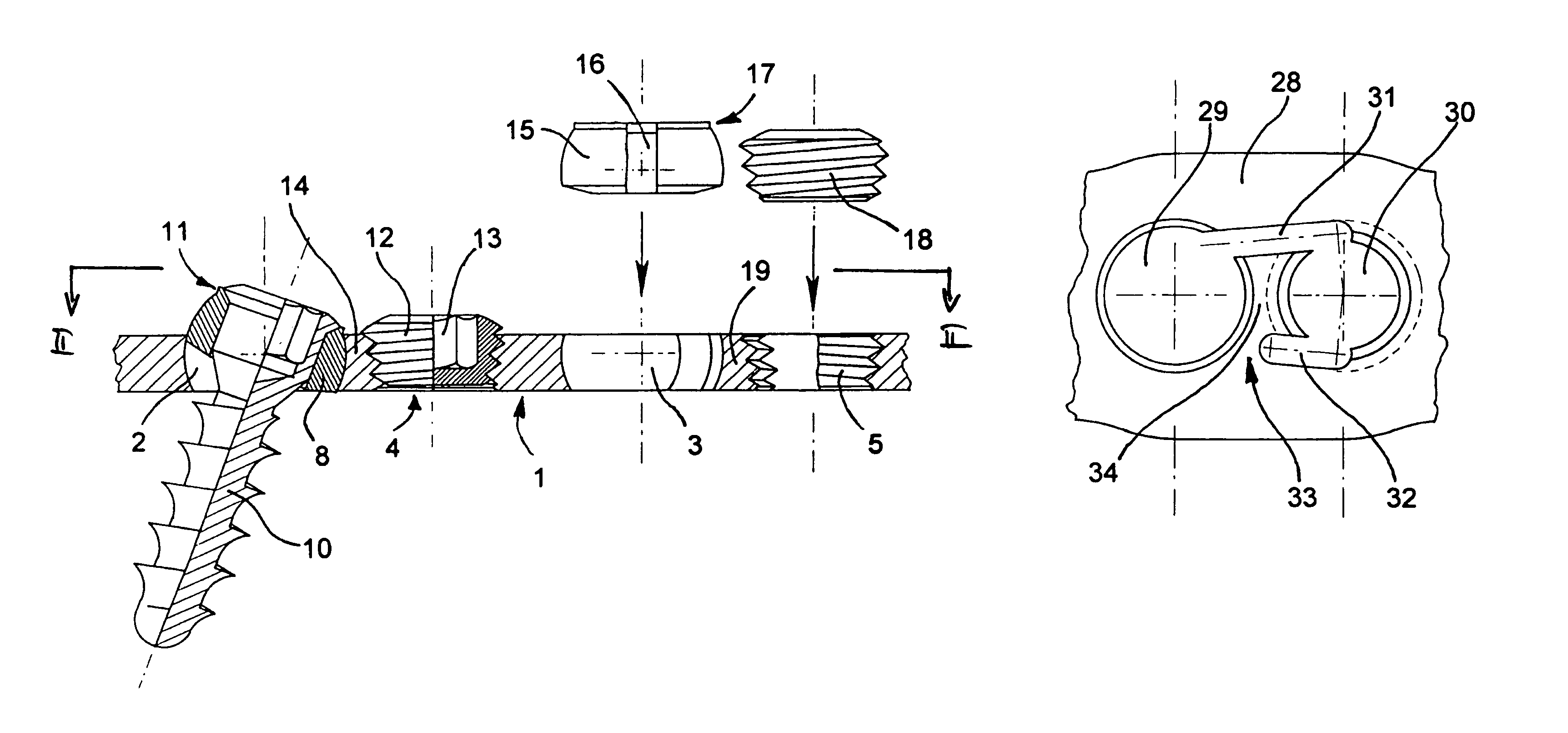
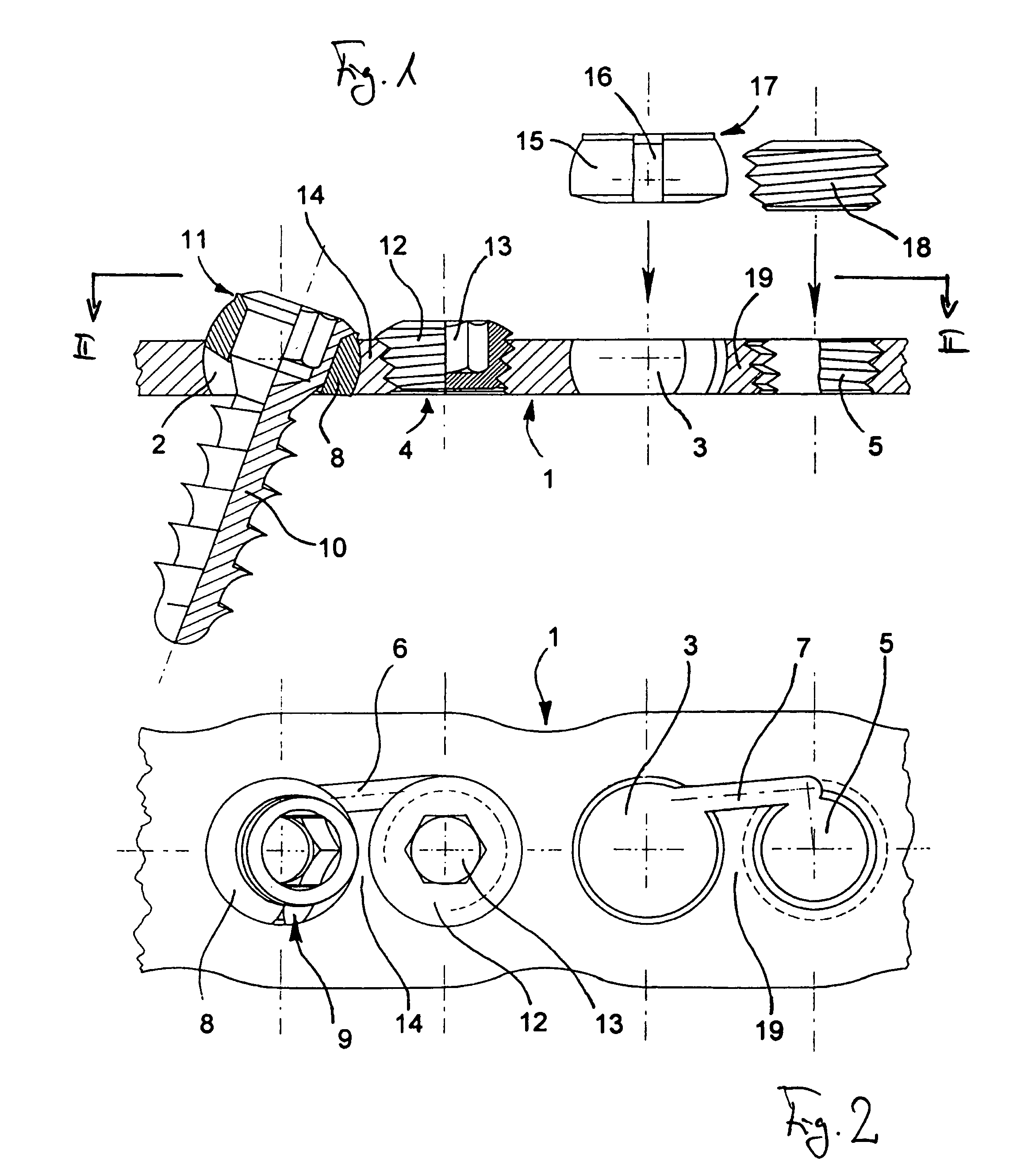
[0040]The ball socket 8 fits accurately and rotatably in the spherical receiving bore 2 and is pivotable in all directions. The ball socket 8 has a slot 9, which permits a slight deformation of the ball socket 8. In addition, the ball socket 8 has a central cylindrical bore into which the half-cut bone screw 10 is inserted rotatably and displaceably in clamping seating or play seating.

[0041]At its upper end, the ball socket 8 has a circular ring collar 11 which limits the otherwise freely selectable swiveling movement of the screw axis to the desired extent structurally.

[0042]A short conical thread pin 12 with a hexagon socket 13 is screwed as a locking screw into the clamping bore 4. By screwing the tapered thread pin 12 into the clamping bore 4, a web 14 is pressed into the spherical receiving bore, so that the osteosynthesis plate 1, the ball socket 8 and the bone screw 10 are tightened against one another. When tapered threaded pin 12 is tightened firmly, this results in an angu...


PUM


Abstract

To be able to secure a bone screw, in particular one that can be aligned polyaxially, especially fixedly and nevertheless easily and detachably in an osteosynthesis plate or a comparable implant, a clamping bore is proposed in addition to a receiving bore, whereby the receiving bore holds a bone screw directly or indirectly, and the clamping bore runs essentially perpendicular to the osteosynthesis plate or parallel to the receiving bore, and with a recess in the area of the bores, preferably between the bores, being arranged in relation to the receiving bore in such a way that widening of the clamping bore results in a constriction of the receiving bore.

Description

CROSS REFERENCE TO RELATED APPLICATION[0001]Applicant claims priority under 35 U.S.C. §119 of German Application No. 103 26 643.7 filed Jun. 11, 2003. Applicant also claims priority under 35 U.S.C. §119(e) of Provisional Application No. 60 / 477,647 filed Jun. 11, 2003.BACKGROUND OF THE INVENTION[0002]1. Field of the Invention[0003]This invention relates to an osteosynthesis plate or a comparable implant plus a ball socket for such an implant.[0004]2. The Prior Art[0005]A problem frequently encountered in orthopedic surgery is that bone fragments which have been separated due to a fracture must be joined together for the purpose of support and / or healing. Osteosynthesis plates and comparable orthopedic implants have proven suitable for this purpose. They have specially designed receiving bores to receive bone screws. The implants are intended in particular for fixation of unstable fractures of large or small tubular bones as well as compact bones such as vertebral bones, wrist bones o...

Claims


Application Information

Patent Timeline
Patent Type & Authority Patents(United States)
IPC IPC(8): A61B17/80A61B17/58A61B17/70
CPCA61B17/8061A61B17/8047A61B17/7059A61B17/8052
Inventor MUCKTER, HELMUT
Owner MUCKTER HELMUT
Why Eureka
Try Eureka