Electronic parking brake device

a technology of electronic brakes and parking brakes, which is applied in the direction of fluid actuated drum brakes, braking systems, gearing, etc., can solve the problems of difficult to reduce the size of electronic drum brakes and difficult to use electronic drum brakes as drum parking brakes of small vehicles, so as to achieve the effect of reducing the size of products

Active Publication Date: 2021-08-19
HYUNDAI MOBIS CO LTD
View PDF4 Cites 0 Cited by
  • Summary
  • Abstract
  • Description
  • Claims
  • Application Information

AI Technical Summary

Benefits of technology

[0019]The electronic parking brake device in accordance with the embodiment of the present disclosure may perform main braking using hydraulic pressure. Furthermore, while rotated by the operation of the motor part, the operating part may push the piston part disposed on both sides of the operating part, thereby providing a parking braking force. At this time, since the operating part and the piston part are arranged in a line, the size of a product can be reduced, which makes it possible to apply the product to a small vehicle.

Problems solved by technology

In the related art, however, since the parking part and the hydraulic piston serving as the main brake part are separated from each other in a 2-row structure, it is difficult to reduce the size of the electronic drum brake.
Thus, it is difficult to use the electronic drum brake as a drum parking brake of a small vehicle.

Method used


Image

  • Electronic parking brake device
  • Electronic parking brake device
  • Electronic parking brake device

Examples


Embodiment Construction

[0028]Hereinafter, an electronic parking brake device will be described below with reference to the accompanying drawings through various exemplary embodiments. It should be noted that the drawings are not to precise scale and may be exaggerated in thickness of lines or sizes of components for descriptive convenience and clarity only. Furthermore, the terms as used herein are defined by taking functions of the invention into account and can be changed according to the custom or intention of users or operators. Therefore, definition of the terms should be made according to the overall disclosures set forth herein.

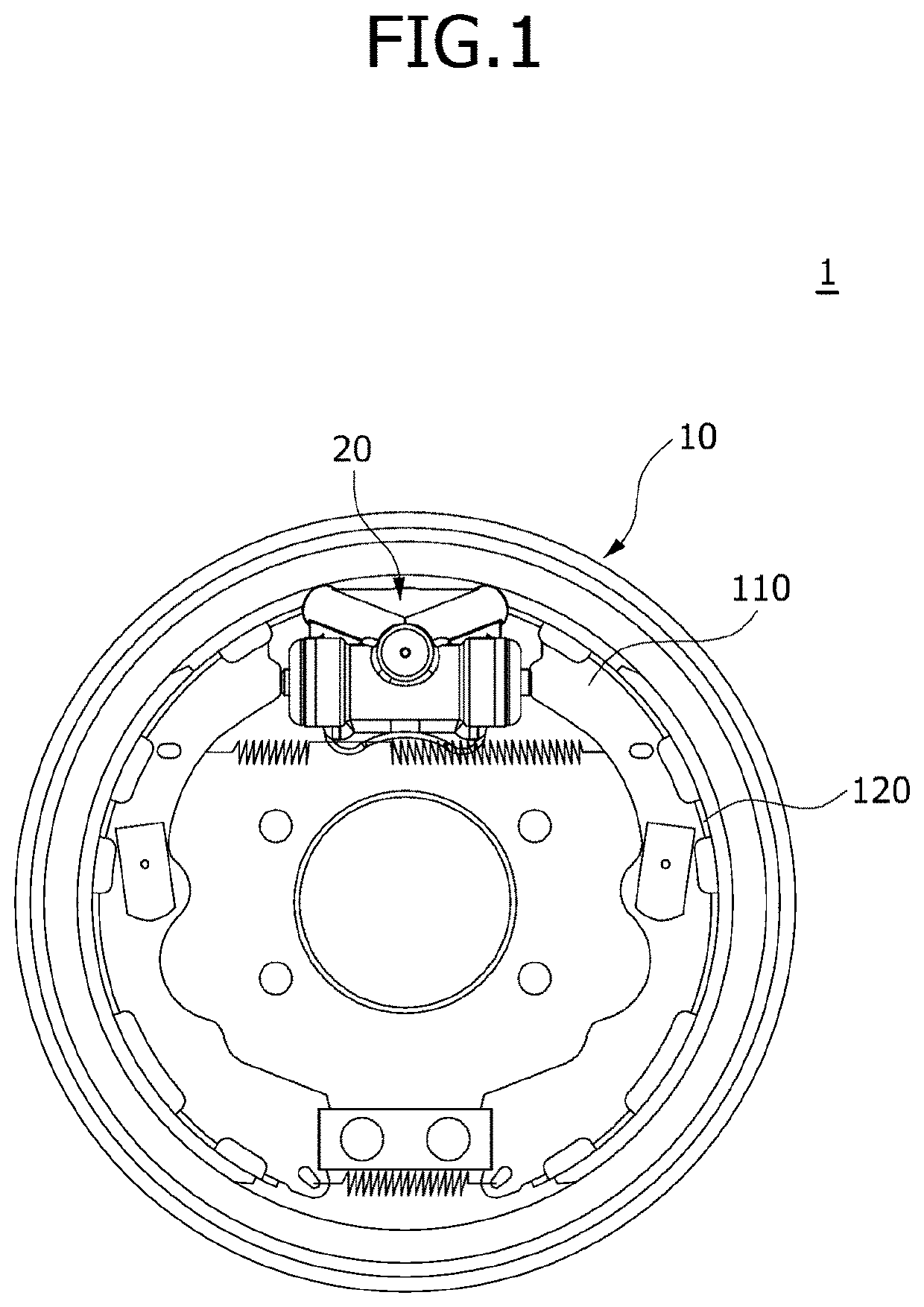
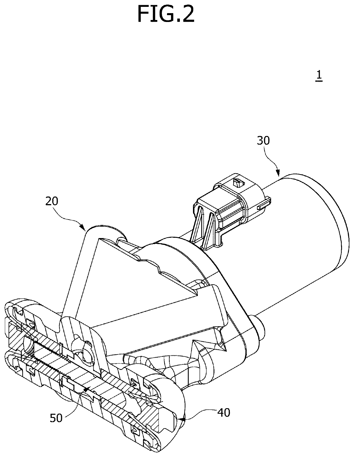
[0029]FIG. 1 is a diagram schematically illustrating an electronic parking brake device in accordance with an embodiment of the present disclosure, and FIG. 2 is a cross-sectional view schematically illustrating the electronic parking brake device in accordance with the embodiment of the present disclosure. Referring to FIGS. 1 and 2, the electronic parking brake device 1 in...


PUM


Abstract

An electronic parking brake device may include: a plate part having a brake shoe rotatably mounted thereon; a housing part mounted on the plate part and configured to guide hydraulic pressure; a motor part mounted on the housing part, and driven when power is applied thereto; a piston part mounted on the housing part, and moved by hydraulic pressure so as to operate the brake shoe; and an operating part embedded in the housing part, and driven by the motor part so as to move the piston part.

Description

CROSS-REFERENCE TO RELATED APPLICATION[0001]This application claims priority from and the benefit of Korean Patent Application No. 10-2020-0017301, filed on Feb. 13, 2020, which is hereby incorporated by reference for all purposes as if set forth herein.BACKGROUNDField[0002]Exemplary embodiments of the present disclosure relate to an electronic parking brake device, and more particularly, to an electronic parking brake device which can implement electronic parking braking and traveling braking by hydraulic pressure in a small vehicle with a small wheel layout.Discussion of the Background[0003]In general, an electronic drum brake is designed to have a structure in which a parking part and a hydraulic piston serving as a main brake part are separated from each other. When hydraulic pressure is applied to the hydraulic piston during main parking, a shoe assembly pressurizes a drum to reduce the speed of the vehicle. When the vehicle is parked, an actuator is operated to rotate a worm g...

Claims


Application Information

Patent Timeline
Patent Type & Authority Applications(United States)
IPC IPC(8): B60T13/58F16D51/24F16D65/22B60T1/06B60T1/00B60T13/74F16H25/20H02K7/06
CPCB60T13/58F16D51/24F16D65/22B60T1/067F16D2121/04B60T13/746F16H25/20H02K7/06B60T1/005B60T13/741F16D2121/24F16D2125/40F16D2123/00F16D2125/52F16D51/18B60T13/74F16H57/02F16H1/16F16D2121/02F16D2125/06F16D2125/08F16D2125/42F16H2025/2046F16H2025/2084
Inventor JO, CHI HOON
Owner HYUNDAI MOBIS CO LTD
Why Eureka
Try Eureka