Cutter Head of a Manually Guided Implement

a technology of manual guided or portable implements and cutter heads, which is applied in the direction of metal working apparatus, agricultural tools and machines, agriculture, etc., can solve the problems of unmodified contact plates, achieve precise adaptation of inherent frequencies, prevent the formation of operational oscillation excitations, and dissipate oscillation excitation energy

Inactive Publication Date: 2010-09-16
ANDREAS STIHL AG & CO KG
View PDF11 Cites 1 Cited by
  • Summary
  • Abstract
  • Description
  • Claims
  • Application Information

AI Technical Summary

Benefits of technology

[0021]The contact or pressure piece preferably has a respective radial dampening projection for each blade wing. Consequently, the contact or pressure piece of the present application deviates from the hereto fore known circular shape, and in the direction of the blade wing or blade wings has a longitudinally extended shape. Due to the abutment against the blade wing, the radially projecting dampening portion of the dampening projection prevents the formation of an in particular harmonic oscillation of the blade wing. In addition, the flat or laminar abutment acts as a friction dampener. The type of construction of the dampening projection, which is longitudinally extended in the radial direction, causes an only slight application of mass that is capable of natural oscillation. On the whole, the tendency of the blade wings toward oscillations is thereby significantly reduced or even entirely eliminated.
[0032]A protection against losing the contact or pressure piece having the at least one dampening projection relative to the cutting blade is advantageously provided. During replacement of the cutting blade, or during maintenance work thereon, the contact or pressure piece cannot become lost. In addition, the protection against losing holds the dampening projection in the prescribed rotational angle position relative to the blade wing, thus avoiding incorrect assembly.

Problems solved by technology

Furthermore, the unmodified contact plate permits the installation of other tools where the use of contact or pressure pieces having dampening projections is not required or not desired.

Method used


Image

  • Cutter Head of a Manually Guided Implement
  • Cutter Head of a Manually Guided Implement
  • Cutter Head of a Manually Guided Implement

Examples


Embodiment Construction

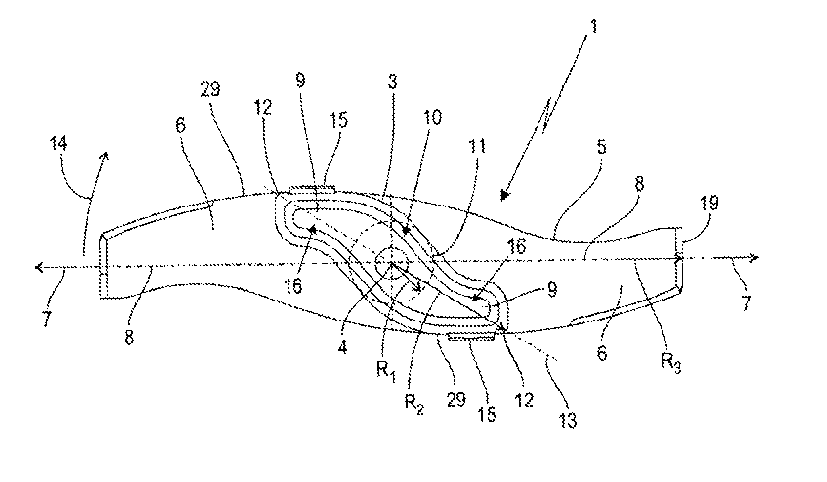
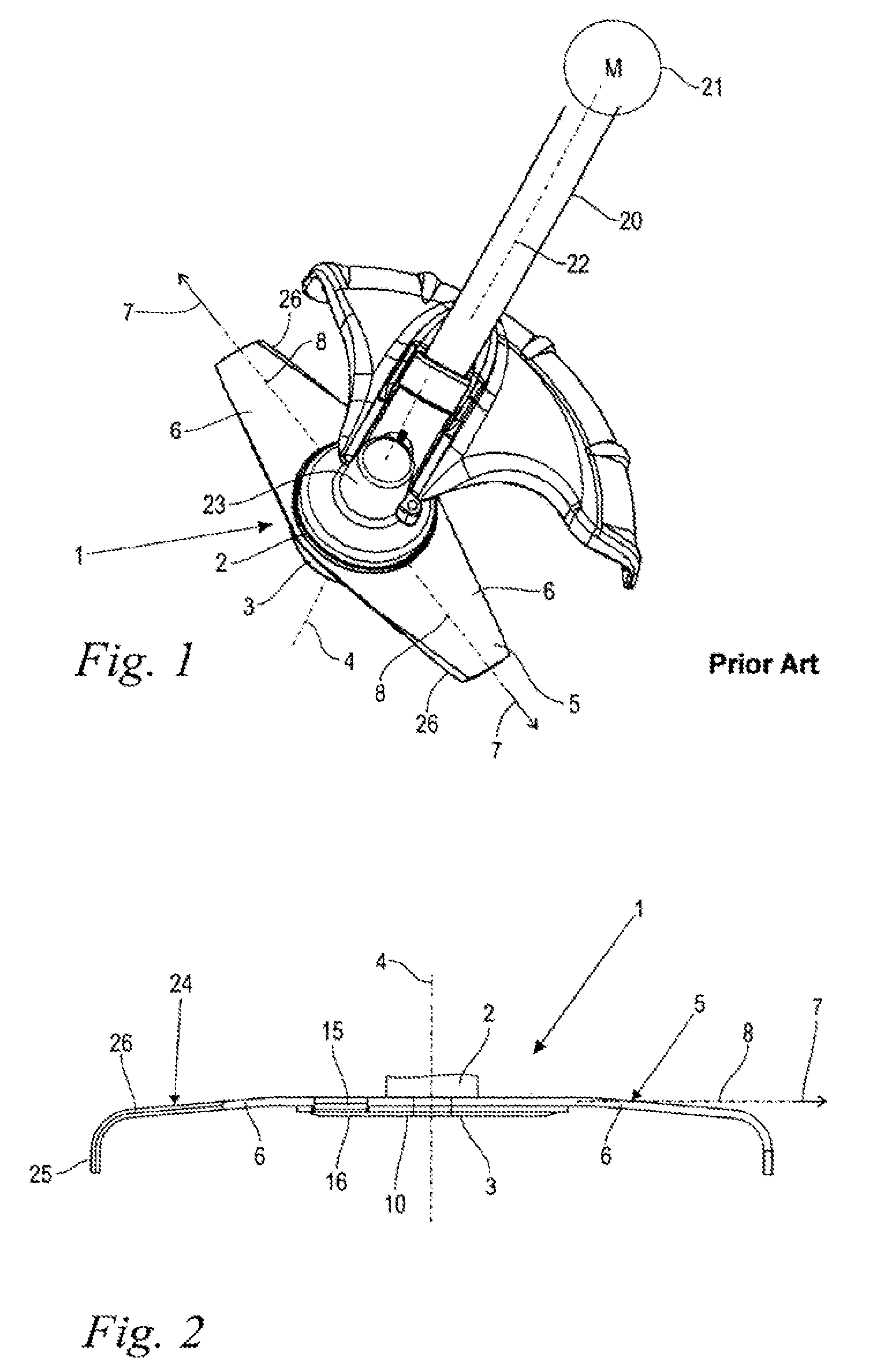
[0034]Referring now to the drawings in detail, the perspective view of a partially schematically illustrated, manually guided or portable implement shown in FIG. 1 by way of example of a brushcutter, includes a blade or cutter head 1 and an indicated drive motor 21. The drive motor 21 is an internal combustion engine, although it can also be an electric motor for the power supply or battery operation. Furthermore, other motor-driven implements, such as a manually guided lawn mower, a riding mower, or the like can also be provided. The drive motor 21 rotatably drives a non-illustrated drive shaft that is guided in a guide tube 20. Disposed at that end of the guide tube 20 that is opposite the drive motor 21 is a gear mechanism head 23 having a miter gear. There, the rotational movement of the drive shaft in the guide tube 20 is transferred to the cutter head 1.

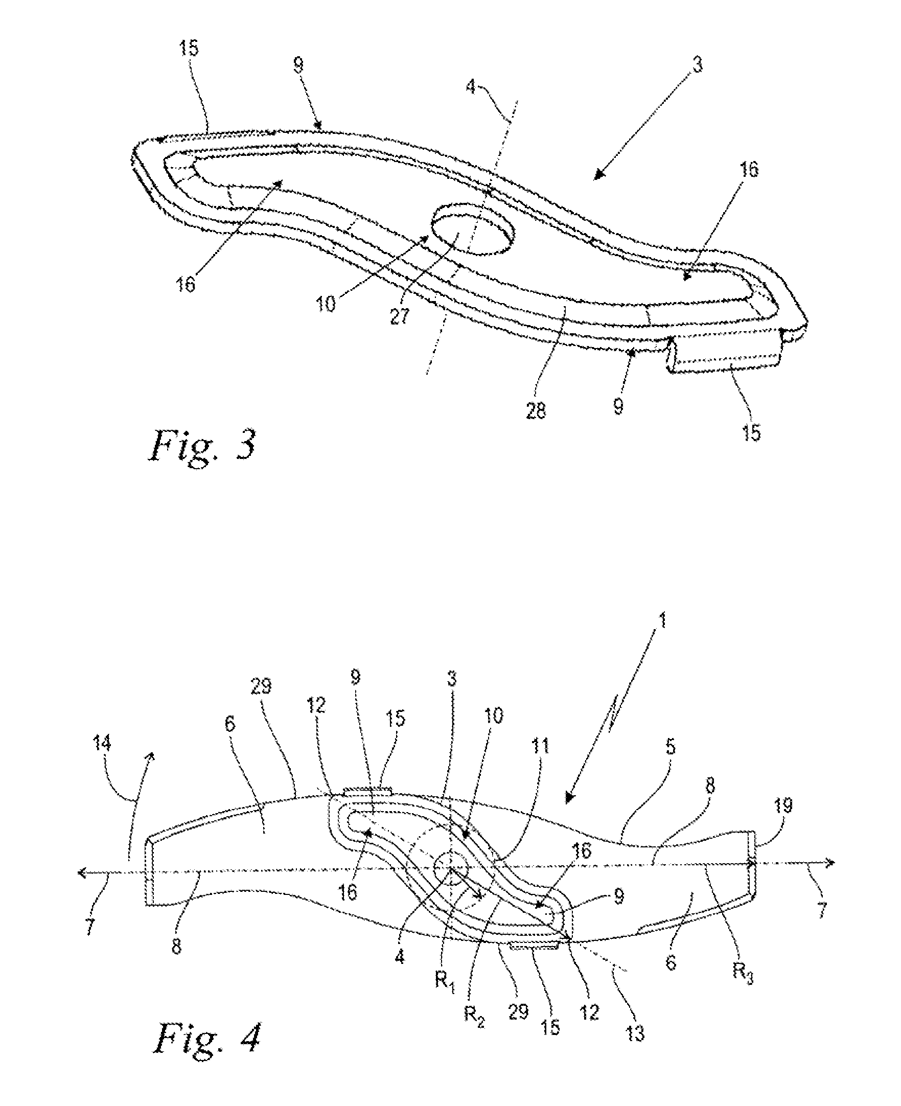
[0035]The cutter head 1 includes two contact or pressure pieces 2,3, whereby the upper contact or pressure piece 2, which fac...


PUM


Abstract

A cutter head of an implement, comprising a cutting blade rotatably drivable about an axis of rotation. The cutting blade is provided with at least two blade wings that extend along a longitudinal axis in a radial direction relative to the axis of rotation. The cutting blade is clamped between two contact or pressure pieces, at least one of which is provided with at least one radially extending dampening projection that rests against at least one of the blade wings.

Description

[0001]The instant application should be granted the priority date of Mar. 14, 2009, the filing date of the corresponding German patent application 10 2009 013 277.5.BACKGROUND OF THE INVENTION[0002]The present invention relates to a cutter head of a manually guided or portable implement.[0003]Brushcutters or trimmers, lawn mowers or the like have a cutter head with a cutting blade that is rotatably drivable about an axis of rotation and that is clamped between two contact or pressure pieces. A first contact or pressure piece is formed by a so-called contact plate that is disposed on the side facing the motor and that has a centrally projecting shaft-end pivot. The cutting blade is placed upon the shaft-end pivot via a central shaft opening, and is brought into contact against the contact plate. Finally, the other contact or pressure piece, which is embodied in the form of a circular disk, is placed upon the shaft-end pivot and is preloaded in the axial direction relative to the cont...

Claims


Application Information

Patent Timeline
Patent Type & Authority Applications(United States)
IPC IPC(8): A01D34/73
CPCA01D34/733
Inventor APFEL, NORBERTTHEILE, MARC
Owner ANDREAS STIHL AG & CO KG
Why Eureka
Try Eureka