Ergonomic tubing attachment for medical apparatus

a tubing attachment and ergonomic technology, applied in the field of tubing attachment mechanisms, can solve the problems of significant surgeon fatigue in prolonged use of surgical instruments

Active Publication Date: 2019-08-27
INTEGRA LIFESCIENCES ENTERPRISES LLLP
View PDF79 Cites 3 Cited by
  • Summary
  • Abstract
  • Description
  • Claims
  • Application Information

AI Technical Summary

Benefits of technology

[0013]It has been identified that a significant portion of surgeon fatigue in prolonged use of surgical instruments is due to the rotational twist of the tubing. The torque of the tubing attachments provides a resistance to rotation that the surgeon has to continuously oppose. An advantage of this invention is the elimination of such twist.
[0014]Briefly and in general terms, some embodiments of the present invention provide mechanisms in a tubing attachment joint design to dynamically neutralize this twist. The first mechanism is a molded swivel joint that can be snapped into a groove of a luer device. The swivel extends out from the center where a cradle is provided to capture one tube. This geometry allows the tubing to rotate without twisting eliminating the need for surgeons to resist twist. The second mechanism is the paired choice of materials and geometric tolerances between the tubing inner diameter and a male luer fitting. The design is such that vacuum leaks are not formed while the tubing can rotate in the joint with very little application of rotational moment. Thus the twist in the vacuum tubing can be eliminated regardless of coiling of the remaining length of the tubing.
[0017]In some embodiments, a medical apparatus may include a handpiece and a tube. Moreover, in various embodiments, the tube may be connected to the handpiece through a swivel joint which allows the tube to rotate circumferentially with respect to the handpiece without axial displacement of the tube.
[0019]In various embodiments, a tubing attachment system for use with an ultrasonic surgical apparatus having a handpiece and an aspiration tube to be connected proximally to the handpiece, wherein the tubing attachment system may comprise a tubing attachment component. The tubing attachment component may comprise a longitudinal throughbore and a circumferential groove on an external frame surface. In some embodiments, the tubing attachment component may comprise a proximal end portion configured to attach to the aspiration tube and a distal end portion configured to attach to the handpiece. In some embodiments, the tubing attachment system may include a capture component comprising a frame having a front side and an opposing back side and a longitudinal frame opening extending between the front side and the back side. In various embodiments, the longitudinal frame opening may be defined by a plurality of locking protrusions, each locking protrusion may have a proximal end and a distal free end, wherein the proximal end projects from the frame adjacent the front side and the distal free end adjacent the back side. In some embodiments, each locking protrusion may narrow the longitudinal frame opening from the front side to the back side. Moreover, in some embodiments, the frame between the front side of the frame and the distal free ends of the plurality of locking protrusions may be longitudinally held between the longitudinal extent of the circumferential groove of the tubing attachment component while allowing rotation of the capture component about the tubing attachment component. In various embodiments, the plurality of locking protrusions may allow the capture component to rotate about the tubing attachment component when a threshold external force is applied to the tubing attachment component.

Problems solved by technology

It has been identified that a significant portion of surgeon fatigue in prolonged use of surgical instruments is due to the rotational twist of the tubing.

Method used


Image

  • Ergonomic tubing attachment for medical apparatus
  • Ergonomic tubing attachment for medical apparatus
  • Ergonomic tubing attachment for medical apparatus

Examples


Embodiment Construction

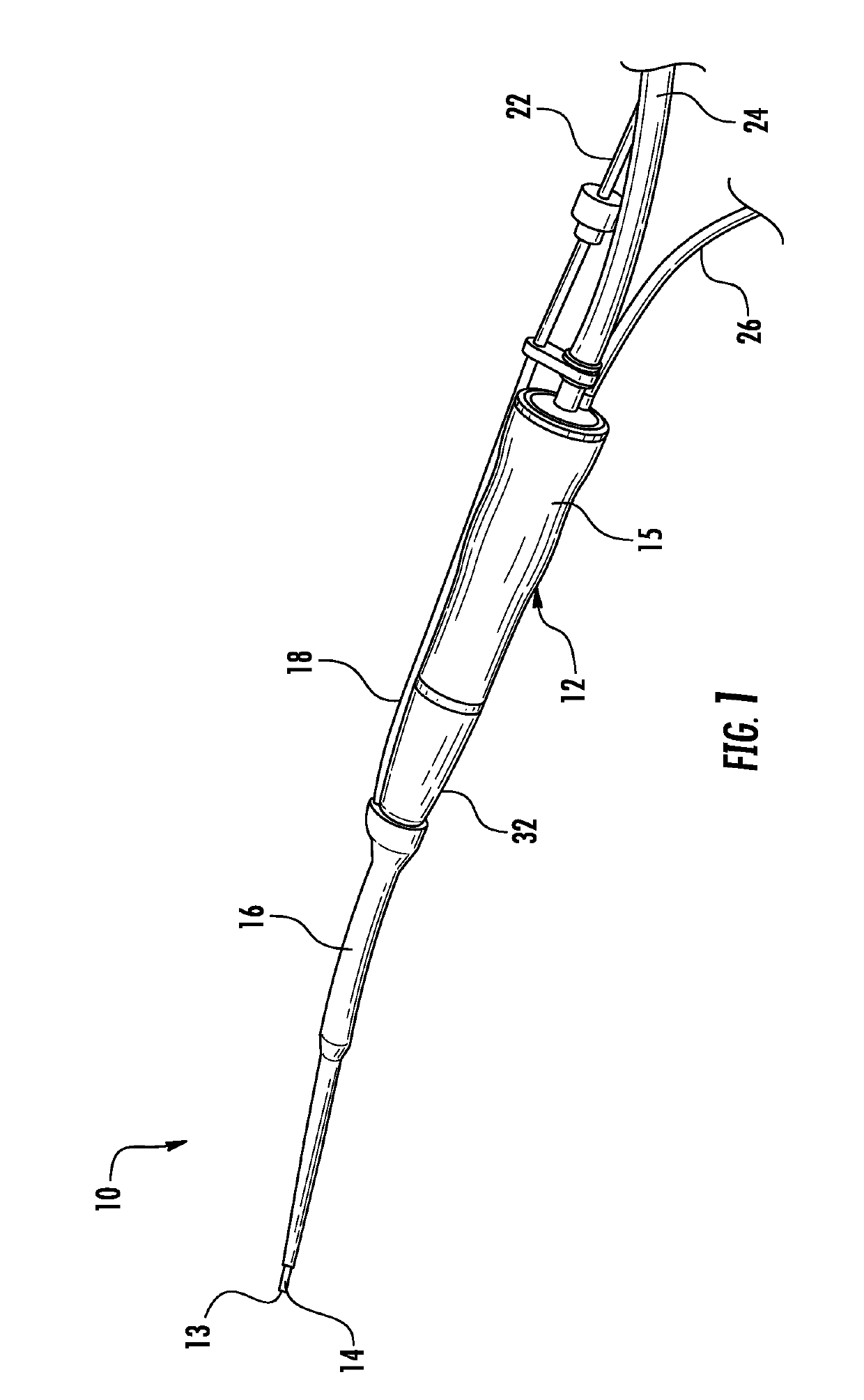
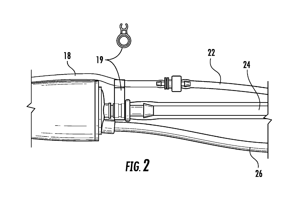
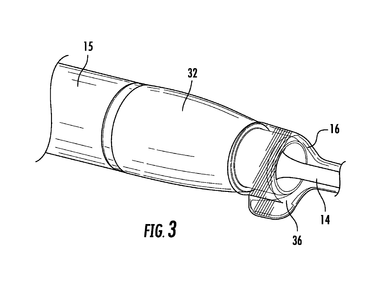
[0057]Embodiments of the presently disclosed tubing attachment system will now be described in detail with reference to the drawings, in which like reference numerals designate identical or corresponding elements in each of the several views. As used herein, the term “distal” refers to that portion of the instrument, or component thereof which is farther from the user while the term “proximal” refers to that portion of the instrument or component thereof which is closer to the user during normal use. The terms “ultrasonic horn,”“ultrasonic tip,”“ultrasonic aspirating tip,”“ultrasonic surgical aspirating tip,”“aspirating tip,”“ultrasonic surgical tip,”“surgical tip”, “horn” and “tip” are used herein interchangeably. The terms “tube” and “tubing” are used herein interchangeably. The terms “capture component,”“tube clip,”“tubing clip,”“flue tube clip,”“flue tubing clip,”“flue irrigation tube clip,” and “flue irrigation tubing clip” are used herein interchangeably.

[0058]It has been foun...


PUM


Abstract

An ergonomic attachment system for connecting an irrigation tube or an aspiration tube to a surgical handpiece that reduces surgeon wrist fatigue due to tubing twist. The tube is connected to the handpiece through a swivel joint which allows the tube to rotate circumferentially with respect to the handpiece and self-adjust to a neutral position to relieve the twist.

Description

CROSS-REFERENCE TO RELATED APPLICATIONS[0001]This application claims priority to and benefit under 35 U.S.C. § 119 to U.S. Provisional Application No. 62 / 424,589, filed Nov. 21, 2016 and U.S. Provisional Application No. 62 / 340,591, filed May 24, 2016, and also to U.S. Design application Ser. No. 29 / 565,482, filed May 20, 2016 and U.S. Design application Ser. No. 29 / 580,596, filed Oct. 11, 2016, the entire contents of each of which are hereby incorporated by reference.BACKGROUND OF THE INVENTION[0002]The embodiments of the present invention relate generally to tubing attachment mechanisms, and more particularly, to ergonomic tubing attachments for use in medical apparatus such as ultrasonic surgical aspirators.[0003]Ultrasonic aspiration has become the standard of care for removal of tumors and diseased tissue in neurosurgery and general surgery. Ultrasonic aspirators are used for ultrasonic fragmentation of tissue at an operation site and aspiration of the tissue particles and fluid...

Claims


Application Information

Patent Timeline
Patent Type & Authority Patents(United States)
IPC IPC(8): A61M1/00A61B1/00A61B1/005A61B17/32
CPCA61B2217/005A61B2217/007A61B17/320068A61B2017/320084A61B2017/32007A61B1/00128A61B1/0014A61B1/00131A61B1/00135A61B1/0051A61M1/774A61M1/86
Inventor MANANDHAR, PRAKASHCOTTER, DANIEL J.KETELHOHN, ROBERT A.GOULD, PETER L.METIVIER, TODD
Owner INTEGRA LIFESCIENCES ENTERPRISES LLLP
Why Eureka
Try Eureka