Double roll lead belt forming machine

A technology of forming machine and lead strip, applied in the field of counter-roll lead strip forming machine, can solve the problems of reduced production flexibility, easy contamination of cooling liquid, spray influence, etc., and achieves improved production flexibility, appearance quality assurance, cooling mild effect

Active Publication Date: 2016-01-13
JIANGSU SANHUAN IND HLDG CO LTD
View PDF9 Cites 0 Cited by
  • Summary
  • Abstract
  • Description
  • Claims
  • Application Information

AI Technical Summary

Problems solved by technology

[0003] If the lead strip with a width of more than 200mm is produced, the steel strip will always be in a tempering state due to the short circulation stroke of the steel strip and the direct spraying of the inner and outer layers. After a long time, the steel strip will be thermally deformed and unable to Maintaining a flat state will affect the forming lead belt. In severe cases, continuous casting will not be possible. The steel belt needs to be replaced after a short period of time, such as within a week, which seriously affects the normal use of the equipment and increases equipment maintenance. costs, reducing manufacturing efficiency
[0004] The width of the lead strip formed by this type of equipment is determined by the groove width of the forming roller, so once the fixed roller is installed, only one specification of lead strip can be produced, and different rollers must be replaced when producing rough lead strips of different specifications , the production flexibility is greatly reduced
[0005] In addition, the external spray coolant cannot be effectively controlled and recovered. Due to direct contact with the outside world, the coolant is easily polluted, and dust, oil and other debris will fall into the coolant, which reduces the quality of the coolant. shower effect
[0006] In order to meet the market demand, it is now necessary to develop a thick lead strip with a width of 400mm and a thickness of 12mm. Therefore, the existing technology has been unable to meet this need

Method used


Image

  • Double roll lead belt forming machine
  • Double roll lead belt forming machine
  • Double roll lead belt forming machine

Examples


Embodiment Construction

[0033] In order to further explain the technical means and functions adopted by the present invention to achieve the intended invention purpose, the structure, features and functions of the present invention will be described in detail below in conjunction with the accompanying drawings and preferred embodiments.

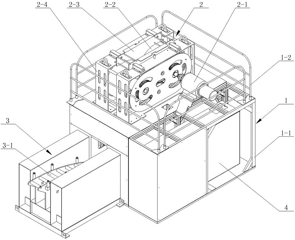
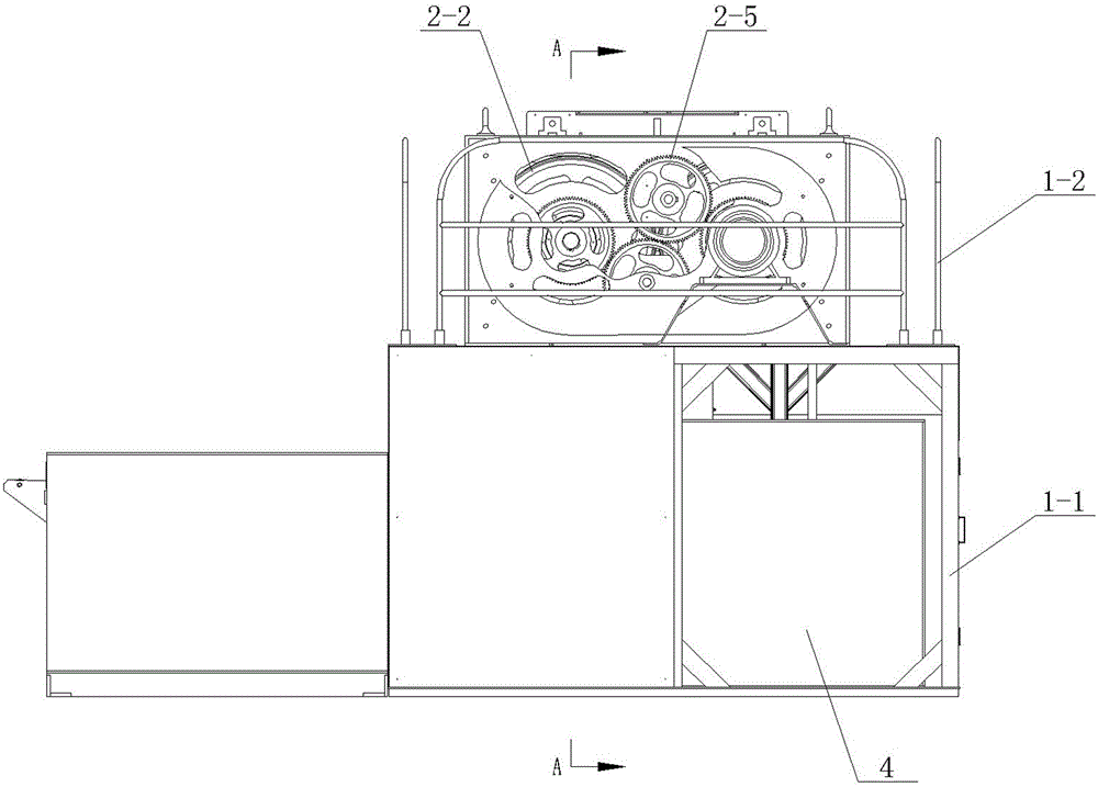
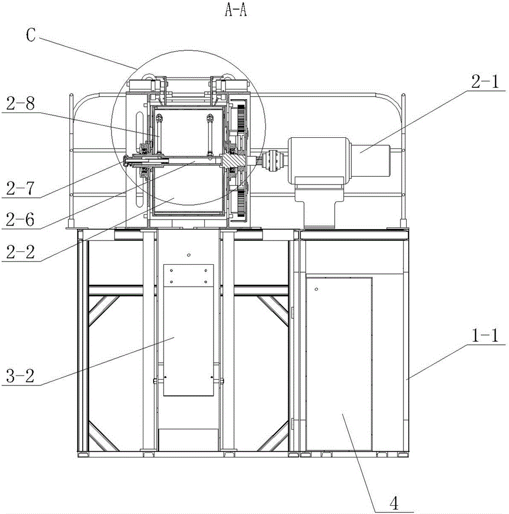
[0034] Such as figure 1 , figure 2 , Figure 5 , Figure 7 Shown is one of the embodiments of the present invention, in this embodiment, the main frame body 1 is provided with the roll-type lead belt forming machine, the main frame body 1 is the main supporting part of the lead belt forming machine, and the inside is provided with a section steel made The support 1-1 is provided with a switchable cabinet door on the side.

[0035] The upper part of the main frame body 1 is provided with a casting part 2 that casts lead liquid into a lead belt, and the main frame body 1 is provided with an output part 3 that accepts the formed lead belt, such as Figure 6 As sho...


PUM

PropertyMeasurementUnit
widthaaaaaaaaaa
thicknessaaaaaaaaaa

Abstract

The invention discloses an opposite-rolling lead belt forming machine. The forming machine is provided with a main frame body; a casting part for casting molten lead into a lead belt is arranged at the upper part of the main frame body; a conveying roller way for bearing the formed lead belt is formed in the main frame body; the casting part is provided with two forming rollers which roll downwards relatively; the holding distance between the two forming rollers is adapted to the thickness of the lead belt to be formed; two forming plates are oppositely arranged above the forming rollers; the rolling plates and the forming rollers form a lead tank for storing the molten lead; cooling devices for cooling roller bodies are arranged in the forming rollers; and the forming plates can be used for adjusting the holding space so as to adjust the width of the lead belt to be formed. The opposite-rolling lead belt forming machine can be used for producing lead belts with different widths and specifications, and is high in production flexibility; the bodies of the forming rollers are provided with hollow interlayer, supporting separating plates are arranged in the interlayer, and thereby the shapes of the bodies of the forming rollers can be effectively kept; and the internally-sealed cooling devices are arranged in the forming rollers, so that the quality of cooling liquid can be effectively kept.

Description

technical field [0001] The invention relates to a counter-roll lead belt forming machine, in particular to a device for casting lead belts using relatively rotating forming rolls. Background technique [0002] At present, the main technologies used in the forming equipment for producing lead strips on the market are as follows: the casting mold adopts rollers with grooves on the outer circle, the grooves are wrapped by steel strips, and the steel strips are always in a state of circular motion. The melted lead liquid is cast in the groove, and the casting mold is cooled at the same time. The cooling system includes an inner spray device and an outer spray device, which sprays and cools the coated lead liquid, so that the lead belt can be cooled during this process. After medium solidification and solidification, it is taken out by the guiding mechanism for subsequent processing. Wherein, the outer spraying device directly sprays the wrapped steel strip. The specifications ...

Claims


Application Information

Patent Timeline
Patent Type & Authority Patents(China)
IPC IPC(8): B22D11/06
Inventor 汪群华卢曦朱晨
Owner JIANGSU SANHUAN IND HLDG CO LTD
Why Eureka
Try Eureka