Axial-flow air inlet mechanism for two-stroke engine

An air intake mechanism, engine technology, used in combustion engines, machines/engines, internal combustion piston engines, etc.

Inactive Publication Date: 2013-03-27
ZHEJIANG OUYAO MACHINERY
View PDF6 Cites 0 Cited by
  • Summary
  • Abstract
  • Description
  • Claims
  • Application Information

AI Technical Summary

Problems solved by technology

There are certain deficiencies in these two air intake methods

Method used


Image

  • Axial-flow air inlet mechanism for two-stroke engine
  • Axial-flow air inlet mechanism for two-stroke engine

Examples


Embodiment Construction

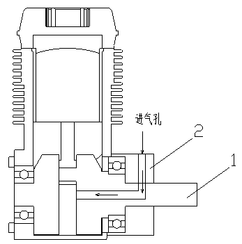
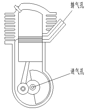
[0015] Such as figure 1 , figure 2 As shown, the axial flow intake mechanism of the two-stroke engine of the present invention includes a crankshaft 1 and a bushing 2, and there is relative movement between the crankshaft 1 and the bushing 2;

[0016] A through hole is opened on the shaft sleeve 2;

[0017] The crankshaft 1 is a hollow shaft; a connecting hole is opened on the position of the crankshaft 1 matching the through hole of the bushing 2, and the connecting hole connects the through hole of the bushing 2 with the hollow part of the crankshaft to form an axial flow valve intake channel ;

[0018] The through hole on the shaft sleeve 2 is externally connected to the carburetor.

[0019] The working principle of the present invention is as follows:

[0020] Crankshaft 1 rotates, and when the connecting hole on the crankshaft 1 communicates with the through hole on the axle sleeve 2, it starts to charge the oil-gas mixture to prepare for the next work.


PUM


Abstract

The invention discloses an axial-flow air inlet mechanism for a two-stroke engine. The axial-flow air inlet mechanism comprises a crankshaft and a shaft bushing, wherein relative motion exists between the crankshaft and the shaft bushing; the shaft bushing is provided with a through hole; the crankshaft is a hollow shaft; and a connecting hole is formed in a position, matched with the through hole of the shaft bushing, of the crankshaft, and an axial flow valve air inlet passage is formed in a manner that the through hole of the shaft bushing and a hollow part of the crankshaft are connected by the connecting hole. When the connecting hole of the crankshaft is communicated with the through hole of the shaft bushing, oil and air mixed gas charging is started so as to prepare to do work next time. According to the axial-flow air inlet mechanism for the two-stroke engine, axial flow valve air inlet can be realized.

Description

technical field [0001] The invention relates to an engine, in particular to an axial flow intake mechanism of a two-stroke engine. Background technique [0002] Existing two-stroke engine, its intake mode generally adopts two kinds, and a kind of is piston valve intake, and another kind is reed valve intake. All there is certain deficiency in these two kinds of intake modes. Contents of the invention [0003] The technical problem to be solved by the present invention is to provide an axial flow intake mechanism of a two-stroke engine, which can realize axial flow valve intake. [0004] In order to solve the above-mentioned technical problems, the technical solution of the axial flow intake mechanism of the two-stroke engine of the present invention is: [0005] Including the crankshaft and the bushing, there is relative movement between the crankshaft and the bushing; there is a through hole on the bushing; the crankshaft is a hollow shaft; a connecting hole is opened o...

Claims


Application Information

Patent Timeline
Patent Type & Authority Applications(China)
IPC IPC(8): F02B29/00F16C3/06F16C9/02
CPCY02T10/146Y02T10/12
Inventor 李怀志刘贝
Owner ZHEJIANG OUYAO MACHINERY
Why Eureka
Try Eureka