Bionic type hydraulic movable artificial vertebral body
A bionic, hydraulic technology, applied in the field of medical devices, can solve problems such as damage to the sealing performance of intervertebral discs
Inactive Publication Date: 2013-04-03
苏州澳森匹科医疗科技股份有限公司
View PDF10 Cites 4 Cited by
- Summary
- Abstract
- Description
- Claims
- Application Information
AI Technical Summary
Problems solved by technology
The effect of rotation force on the annulus fibrosus of the intervertebral disc produces traction and torsion damage, resulting in the micro-avulsion fracture of the annulus fibrosus at the posterior edge of the vertebral body (the annulus fibrosus at the posterior edge of the vertebral body is weak), and the micro-avulsion fracture of the annulus fibrosus leads to a fracture of the intervertebral disc. The original airtight performance is damaged
Method used
View moreImage
Smart ImageViewing Examples
Examples
Embodiment Construction
[0087] After the diseased vertebral body was resected, the artificial vertebral body of this example was inserted, and the pedicle screw was inserted percutaneously to fix the artificial vertebral body of this example. Surgery completed.
Login to View More PUM
 Abstract
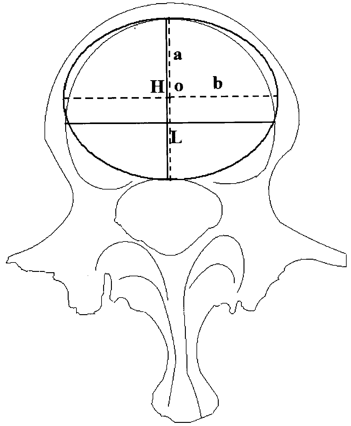
The invention discloses a bionic type hydraulic artificial vertebral body design for spinal physiological function reconstruction. The bionic type hydraulic artificial vertebral body comprises a main cylindrical artificial vertebral body with a core structure, wherein the inner part of the core structure contains pistons (13 and 14) and hydraulic bags (10 and 11). An upper end plate (24) and a lower end plate (25), which are matched with semielliptical (spherical) motion shafts (21 and 22) in structure, are arranged at two ends of each piston. The end plates of the artificial vertebral body are normal adjacent vertebral end plate flats (cemented fixation) or fixed stings (31 and 32) with metal millipores and biological material coating millipores (biological type fixation), and the rear edge of the vertebral body can be further fixedly arranged at a pedicle of vertebral arch through card slots (40 and 41) of the fixed structure of a pedicle of vertebral arch staple bolt (45). The vertebral body design can be further shrunk as a hydraulic artificial intervertebral disc design (60).
Description
technical field [0001] The invention relates to a medical device, in particular to a bionic hydraulic movable artificial vertebral body for reconstructing the physiological function of the spine after spinal defect. Background technique [0002] Spinal fusion technology is the mainstream concept in modern spinal surgery, and it has achieved good clinical results in the treatment of spinal defects. [0003] Clinically, for bursting comminuted vertebral fractures and vertebral tumors, fusion-type artificial vertebral bodies are often used to reconstruct the missing vertebral body parts. However, clinically, the function of two intervertebral discs will be lost after vertebral body excision and fusion for one vertebral body lesion. , that is, fusion of vertebral bodies of at least three segments, sacrificing the motion function of the original spinal vertebral discs. [0004] With the wide clinical application of spinal fusion, new problems caused by complications after fusion...
Claims
Login to View More Application Information
Patent Timeline
 Patent Type & Authority Applications(China)
IPC IPC(8): A61F2/44
CPCA61F2/44A61F2002/30001
Inventor 刘小勇
Owner 苏州澳森匹科医疗科技股份有限公司
Features
- R&D
- Intellectual Property
- Life Sciences
- Materials
- Tech Scout
- Unparalleled Data Quality
- Higher Quality Content
- 60% Fewer Hallucinations
Learn More Browse by: Latest US Patents, China's latest patents, Technical Efficacy Thesaurus, Application Domain, Technology Topic, Popular Technical Reports.
© 2025 PatSnap. All rights reserved.Legal|Privacy policy|Modern Slavery Act Transparency Statement|Sitemap|About US| Contact US: help@patsnap.com


