Bus shearing machine

A technology for shearing machines and busbars, which is applied in the direction of shearing devices, shearing machine equipment, and knives for shearing machine devices, can solve the problems of complex and heavy structures and inconvenient operations, and achieve convenient operation, simple and light structure Lightweight effect

Inactive Publication Date: 2014-08-13
陈伟民
View PDF10 Cites 1 Cited by
  • Summary
  • Abstract
  • Description
  • Claims
  • Application Information

AI Technical Summary

Problems solved by technology

[0002] The current busbar shearing machine has the following disadvantages: the structure is complex and heavy, and the operation is inconvenient

Method used


Image

  • Bus shearing machine
  • Bus shearing machine
  • Bus shearing machine

Examples


Embodiment Construction

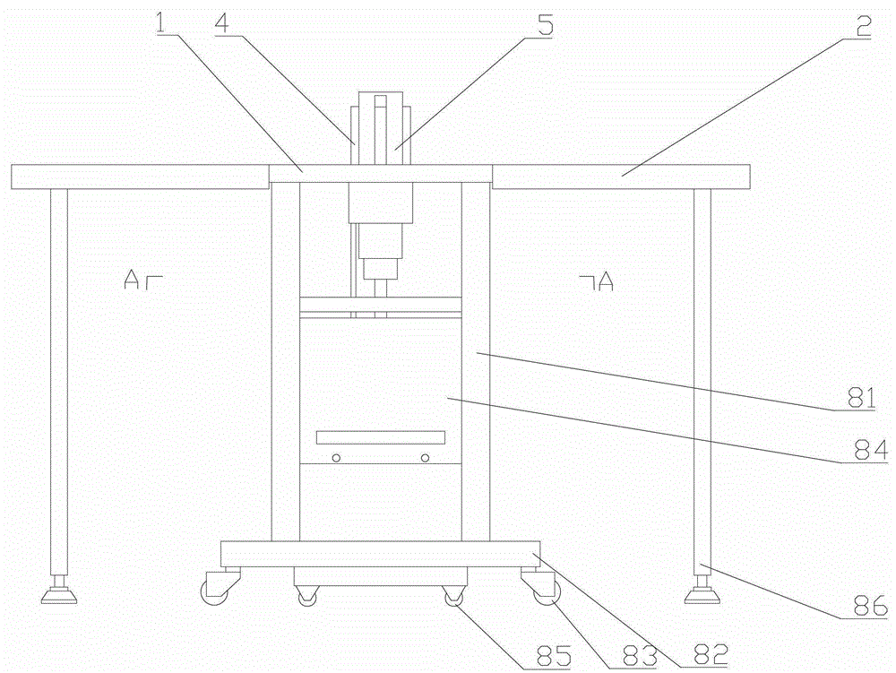
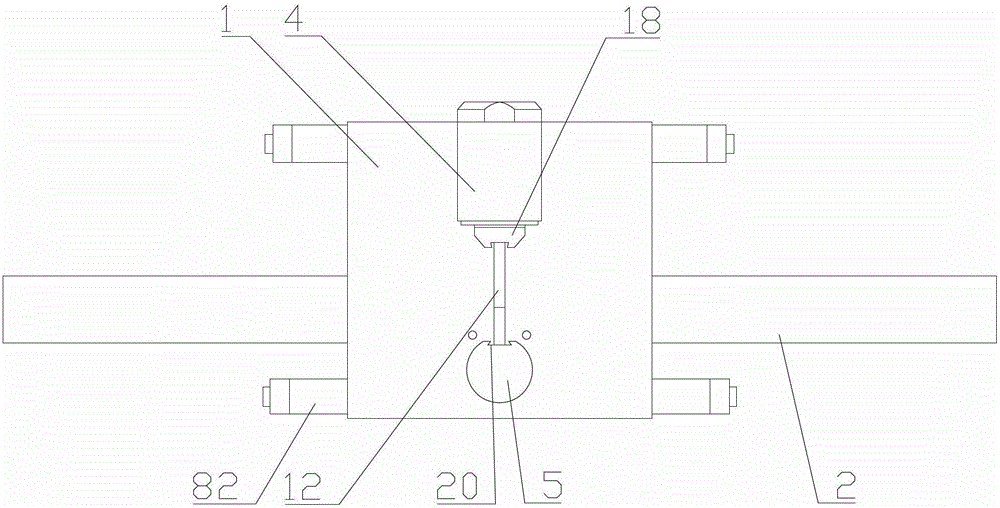
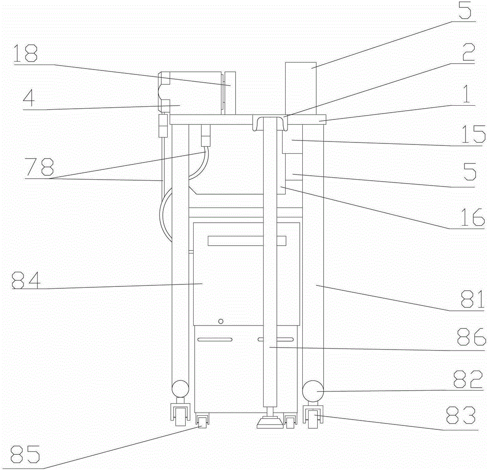
[0028] like Figures 11 to 14 As shown: it includes a platen 1, a support plate 2, an oil cylinder 4 connected with a power device, a pressure head 18, a column 5, and a shearing mold. The platen is used for loading or connecting related components, and longitudinal Arranged oil cylinder sockets 11, guide grooves 12, and column fixing holes 13, the oil cylinder is inserted into the oil cylinder socket through the oil cylinder foot 14 provided on the lower wall of the oil cylinder, the oil cylinder is fixed on the platen by bolts, and the column passes through the column The fixing hole 13 is set on the reinforcing sleeve 15 provided under the fixing hole of the column; the reinforcing sleeve plays the role of strengthening the fixing of the column, and the lower wall of the platen is connected with a reinforcing plate perpendicular to the platen from the rear end of the oil cylinder to the direction of the column 16. The reinforcing plate is connected with the column and the r...


PUM


Abstract

The invention relates to a bus shearing machine which is light and convenient in structure. The bus shearing machine comprises a platen, support plates, an oil cylinder, a pressure head, a column, a shearing die, a punching die and a shearing die. The oil cylinder and the column are fixedly arranged on the platen, and a reinforcing plate vertical to the platen is connected onto the lower wall face of the platen in a direction from the rear end of the oil cylinder to the column. The reinforcing plate is connected with the column and a reinforcing sleeve. A blanking chute is arranged in the upper surface of the reinforcing plate, and a section of guide slot is arranged above the blanking chute correspondingly. The section of guide slot is arranged in a bottom-to-top manner. The pressure head is arranged at the front end of a piston rod of the oil cylinder toward the column, a first dovetail groove is arranged on the side of the pressure head toward the column, and a second dovetail groove is arranged on the side of the column toward the pressure head. The support plates are located on both sides of the platen. A shearing stripping groove passing through the central axis of the column and penetrating through the whole column is arranged in the side face of the column. The opening on one side of the shearing stripping groove is located in the second dovetail groove. The shearing die is arranged on the pressure head and the column. The bus shearing machine provided by the invention has the advantages of simple, light and small structure, convenience in operation and light weight of machine body.

Description

technical field [0001] The invention relates to the field of busbar processing equipment, in particular to a busbar shearing machine with a light structure and multiple functions. Background technique [0002] The current busbar shearing machine has the following disadvantages: the structure is complex and heavy, and the operation is inconvenient. Contents of the invention [0003] The object of the present invention is to provide a busbar shearing machine with a light structure. [0004] The purpose of the present invention is achieved in that it includes a platen, a support plate, an oil cylinder connected to a power unit, a pressure head, a column, and a shearing die, and the platen is successively provided with longitudinally arranged oil cylinder jacks, guide grooves, The column fixing hole, the oil cylinder is inserted into the oil cylinder socket through the oil cylinder foot provided on the lower wall of the oil cylinder, the oil cylinder is fixed on the platen by...

Claims


Application Information

Patent Timeline
Patent Type & Authority Patents(China)
IPC IPC(8): B23D15/14B23D35/00
Inventor 陈伟民
Owner 陈伟民
Why Eureka
Try Eureka