Eavestrough Outlet Cutter

a technology of outlet cutter and eavestrough, which is applied in the direction of metal-working feeding device, manufacturing tool, positioning device, etc., can solve the problems of difficult support of tools and poor edge formation about the opening

Active Publication Date: 2017-12-28
GRANT KEVIN ANTHONY
View PDF14 Cites 1 Cited by
  • Summary
  • Abstract
  • Description
  • Claims
  • Application Information

AI Technical Summary

Benefits of technology

[0010]By providing a frame which is self-supporting for sliding along a trough, a single operator can readily position and align the dies with a desired outlet location for ease of aligning the outlet opening relative to the trough by a single operator.
[0024]Use of a threaded shaft for driving the male die relative to the female die permits the mechanism to be readily adapted for use together with a conventional power drill which is commonly available in the construction industry. The overall size and complexity of the driving linkage can thus be greatly simplified compared to many prior art arrangements while still being easy to use with a minimum effort by a single operator.
[0030]By providing a balanced frame of two side frame portions at opposing sides of the vertical punching axis, the cantilevered supporting arrangement of the dies according to various prior art punching tools can be avoided so that a much simpler and lighter frame structure can be used to provide adequate support to the dies while maintaining a much better alignment of the dies relative to one another than can be achieved with a cantilevered supporting arrangement.
[0036]By shaping the male die to have four corner portions which are each sloped downwardly at two side edges towards a respective apex, the rectangular shaped opening is cut by first piercing the sheet-metal of the bottom flange at the four corners, followed by continued cutting towards a central intermediate location along each of the sides of the rectangular shape. This arrangement provides a much cleaner finished cutting edge about the periphery of the outlet opening, with less curling of the sheet-metal at the edges of the opening than when the punching arrangement begins at the sides of the rectangular shape and finishes at the apexes of the rectangular shape.
[0042]Initially engaging the material to be punched at two diagonally opposed corners of a rectangular opening provides both a clean cut edge at the corners of the opening while also providing a balanced support about the central vertical punching axis, while gradually easing the male die into the die opening of the female die during punching.

Problems solved by technology

Considerable force is required to drive the male die into the die opening of the female die to punch the opening in the bottom flange of the eavestrough, resulting in bending of the frame supporting the dies which can cause misalignment of the dies relative to one another resulting in a poorly formed edge about the opening.
Furthermore, known punch designs are typically quite large, cumbersome and heavy, in part to counterbalance the offset cantilevered support of the dies on the frame, such that the resulting tool is difficult to support in proper alignment relative to an eavestrough by a single operator unless the die is supported on a suitable supporting surface which is undesirable in many environments.

Method used


Image

  • Eavestrough Outlet Cutter
  • Eavestrough Outlet Cutter
  • Eavestrough Outlet Cutter

Examples


Embodiment Construction

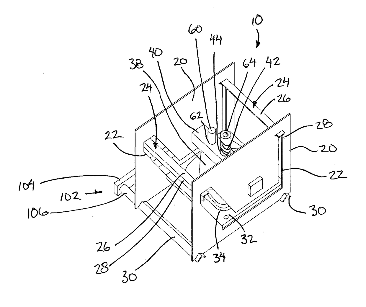
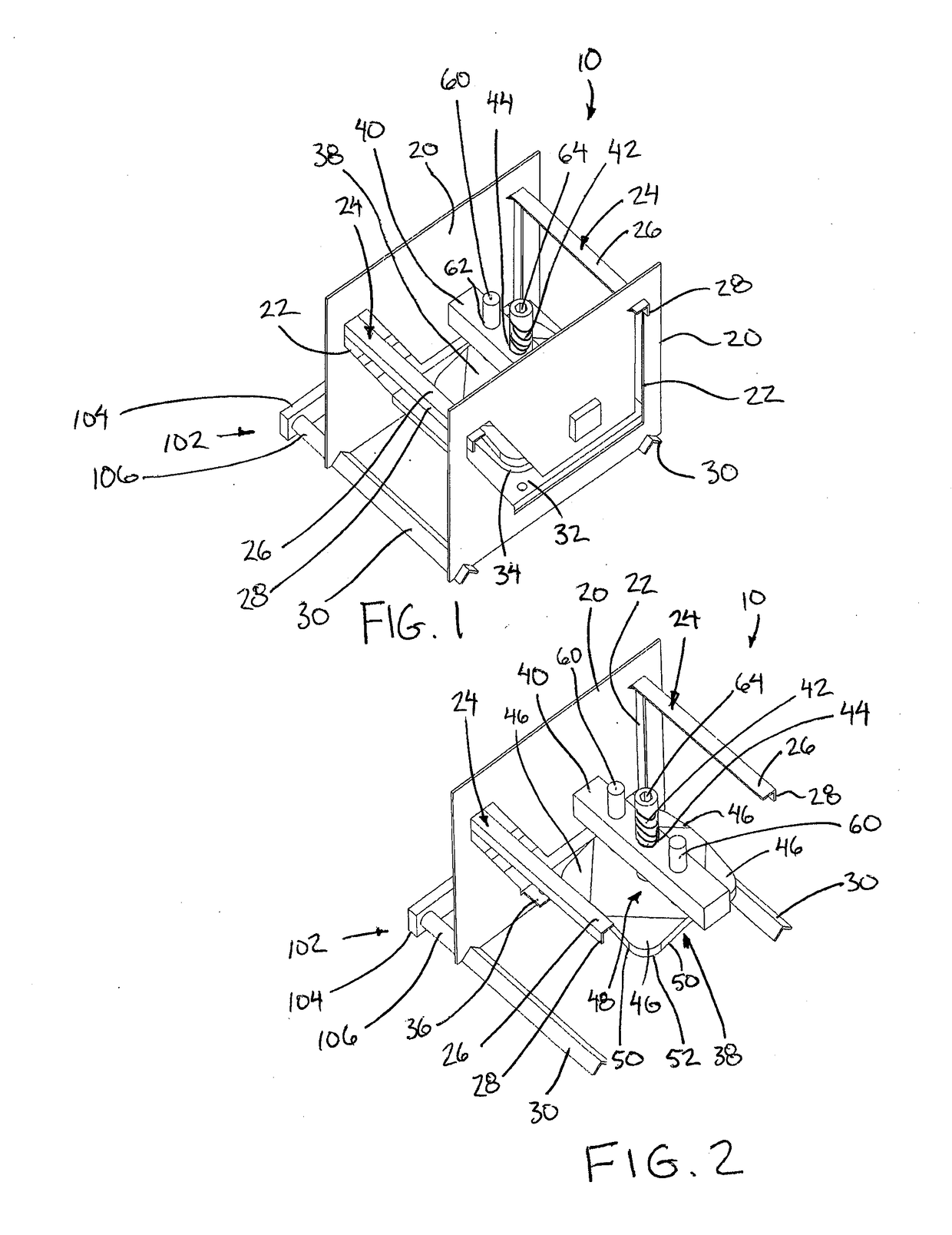
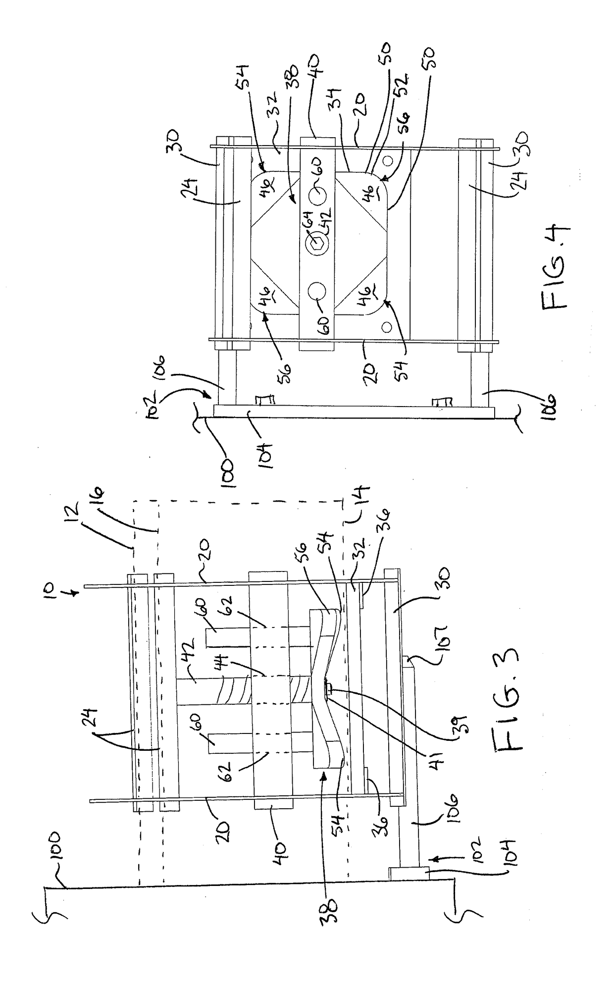
[0053]Referring to the accompanying figures, there is illustrated an eavestrough outlet cutter generally indicated by reference numeral 10. The cutter 10 is particularly suited for use with an eavestrough of the type including a generally flat, vertical rear wall 12, a bottom flange 14 protruding horizontally forward from a bottom edge of the rear wall, and a front wall 16 which is sloped upwardly and forwardly from the forward edge of the bottom flange. The top edge of the front wall 16 is typically folded over inwardly to provide a structurally reinforcing channel at the top edge which is typically slightly lower in elevation than a top edge of the opposing rear wall 12.

[0054]The outlet cutter 10 includes a main frame which includes two side frame portions 20 at laterally opposing sides of the cutter. Each side frame portion comprises a rigid rectangular plate spanning substantially the full height and full width of the cutter. The two plates forming the side frame portions 20 are...


PUM

PropertyMeasurementUnit
angleaaaaaaaaaa
angleaaaaaaaaaa
rotationaaaaaaaaaa

Abstract

An outlet cutter for cutting an outlet opening in an eavestrough has a frame including a trough opening therein arranged to receive the eavestrough therethrough. A female die including a die opening is supported on the frame directly below the trough opening so as to be arranged to be located directly below an eavestrough received through the trough opening. A male die is supported on the frame so as to be movable relative to a female die between a disengaged position spaced above the female die and a punching position fully received within the die opening in the female die using a screw. The frame is self-supported on the eavestrough for sliding. The male die has four corner portions, each formed by two side cutting edges which are sloped downwardly and outwardly towards a respective apex, with two opposed apexes protruding beyond a remainder of the die.

Description

[0001]This application claims the benefit under 35 U.S.C. 119(e) of U.S. provisional application Ser. No. 62 / 354,977, filed Jun. 27, 2016.FIELD OF THE INVENTION[0002]The present invention relates to a cutter for cutting an outlet opening in the bottom flange of an eavestrough having front and rear walls extending upwardly from opposing edges of the bottom flange, and more particularly the present invention relates to an outer cutter for an eavestrough including a frame which supports a female die with a die opening below the bottom flange of the eavestrough and which supports a male die for movement in and out of the die opening in the female die for punching the outlet opening in the bottom flange of the eavestrough.BACKGROUND[0003]A common arrangement for managing precipitation about a building is to provide an eavestrough extending along various edges of the roof of the building. A typical eavestrough includes a bottom flange, a rear wall extending upward from a rear edge of the ...

Claims


Application Information

Patent Timeline
Patent Type & Authority Applications(United States)
IPC IPC(8): B21D28/32B21D43/00B21D45/00B21D28/00
CPCB21D28/32B21D28/00B21D43/00B21D45/00B21D28/26
Inventor GRANT, KEVIN ANTHONY
Owner GRANT KEVIN ANTHONY
Why Eureka
Try Eureka