Ejection mechanism for internal inverted buckle in injection mould

A technology of internal undercut and demoulding mechanism, which is applied in the field of injection molds and can solve problems affecting injection molding, product scrapping, and product quality

Active Publication Date: 2013-04-03
TAIZHOU KAIHUA AUTOMOBILE MOULD CO LTD
View PDF4 Cites 13 Cited by
  • Summary
  • Abstract
  • Description
  • Claims
  • Application Information

AI Technical Summary

Problems solved by technology

[0002] Plastic parts are manufactured with injection molds. If there is an internal undercut in the middle of the plastic product, the traditional method is to use a stripper to push the periphery of the plastic product out of the mold. The buckle is forced to be demoulded outward, and because the outer wall of the inner undercut is in contact with the inner wall of the core insert, the inner wall of the inner undercut is in contact with the outer wall of the ejector rod, and is in a clamped state, and the inner undercut wall is thin, so it is forced to be released outward. When molding, if the inner undercut is flattened or deformed, it will come out, which will affect the quality of the product. If the inner undercut is not flattened or deformed and forced to demould, the inner undercut will be broken, making it It is broken in the core insert, which will not only scrap the product, but also affect the next injection

Method used


Image

  • Ejection mechanism for internal inverted buckle in injection mould
  • Ejection mechanism for internal inverted buckle in injection mould
  • Ejection mechanism for internal inverted buckle in injection mould

Examples


Embodiment Construction

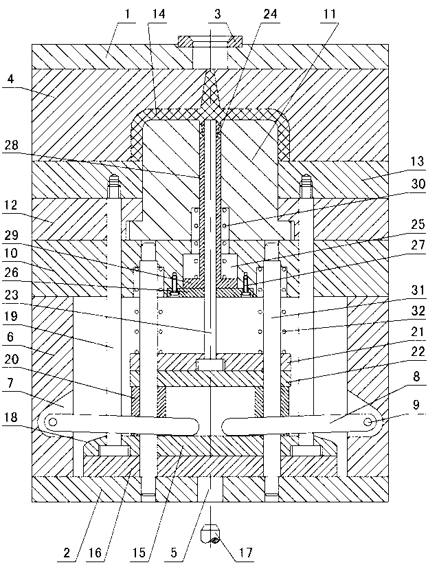
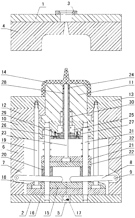
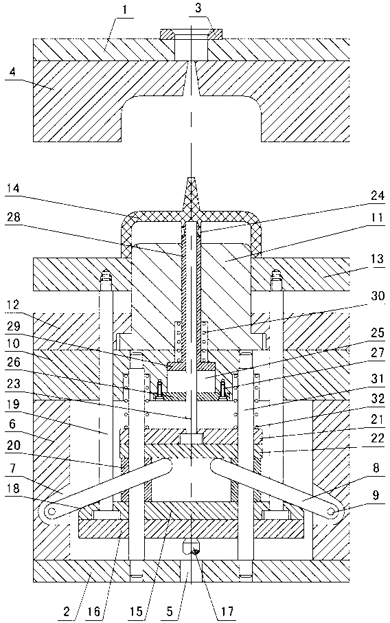
[0011] The present invention relates to an internal buckle release mechanism of an injection mold, such as figure 1 — Figure 4 As shown, it includes the upper doubler plate 1 and the lower doubler plate 2, the positioning ring 3 is installed in the upper doubler plate, the cavity 4 is installed under the upper doubler plate, the perforation 5 is opened in the lower doubler plate 2, and the die foot 6 is installed on the lower doubler plate , there is a swing rod installation groove 7 in the mold foot, a swing rod 8 is installed in the swing rod installation groove, the swing rod is connected with the mold foot 6 through a pin shaft 9, a support plate 10 is installed on the mold foot 6, and the support plate is installed Core insert 11 and core fixing plate 12, stripping plate 13 is installed on the core fixing plate, plastic product 14 is arranged between stripping plate, core insert 11 and cavity 4, and the middle part of the plastic product is formed with internal Undercut...


PUM


Abstract

An ejection mechanism for an internal inverted buckle in an injection mould comprises an upper compound plate and a lower compound plate, wherein a cavity is arranged under the upper compound plate; mould pins are mounted on the lower compound plate; a swing stem mounting groove is formed in each mould pin; a swing stem is mounted in each swing stem mounting groove; a support plate is mounted on the mould pins; a mold core insert and a mold core fixing plate are mounted on the support plate; a striper plate is mounted on the mold core fixing plate; an upper ejector plate A and a lower ejector plate A are arranged between the mould pins; an injection machine ejector rod penetrates a penetration hole to be in contact with the lower ejector plate A; curved contact surfaces are formed on two sides of the upper ejector plate A to be in contact with the swing stem; a material ejection rod is mounted between the upper ejector plate A and the lower ejector plate A and fixed with the striper plate; a stop collar is mounted on the upper ejector plate A; an upper ejector plate B and a lower ejector plate B are mounted on the stop collar; the swing stem is in contact with the lower ejector plate B through the curved contact surfaces; an ejector rod is mounted between the upper ejector plate B and the lower ejector plate B and penetrates the mold core insert to be in contact with a plastic product; a chute is formed in the support plate; a fixing plate is mounted below the chute; a forming sleeve is mounted in the chute and sleeved outside the ejector rod; the upper part of the forming sleeve is matched with an internal inverted buckle; and a forming sleeve return spring is mounted outside the forming sleeve.

Description

technical field [0001] The invention relates to an injection mold, in particular to an undercut ejection mechanism inside the injection mold. Background technique [0002] Using injection mold to make plastic parts, if there is an internal undercut under the middle part of the plastic product, the traditional method is to use a stripper to push the surrounding parts of the plastic product out of the mold, and at the same time, the ejector pin in the middle pushes the inside of the plastic product to be reversed. The buckle is forced to be demoulded outward, and because the outer wall of the inner undercut is in contact with the inner wall of the core insert, the inner wall of the inner undercut is in contact with the outer wall of the ejector pin, and is in a clamped state, and the inner undercut wall is thin, so it is forced to be released outward. When molding, if the internal undercut is flattened or deformed, it will come out, which will affect the quality of the product...

Claims


Application Information

Patent Timeline
Patent Type & Authority Applications(China)
IPC IPC(8): B29C45/40B29C45/33
Inventor 梁正华
Owner TAIZHOU KAIHUA AUTOMOBILE MOULD CO LTD
Why Eureka
Try Eureka