
Long-life extension-resistant threaded mesh belt

A technology of anti-extrusion and longevity, applied in the field of mechanical conveying devices, can solve problems such as broken mesh belts, short service life, and insufficient solder joints, and achieve the effect of firm structure and long service life

Inactive Publication Date: 2013-04-03
FUJIAN SNOWMAN
View PDF4 Cites 7 Cited by
  • Summary
  • Abstract
  • Description
  • Claims
  • Application Information

AI Technical Summary

Problems solved by technology

[0003] The existing spiral conveying mesh belt has great defects and deficiencies in the structure of the connecting plate and the solder joints between the connecting plate and the string rods. Because the riveted joint and the connecting plate are only partially connected during welding, no 360° fusion welding is formed, which makes the mesh belt structure not strong enough; when the mesh belt is squeezed, the hub friction strip directly acts on the end of the string rod At the welding point of the riveting head, it is easy to cause the welding point to be squeezed and damaged
In short, the solder joints are not strong enough and under the action of extrusion force, the existing mesh belt will break at the solder joints
Therefore, the service life is short, and the conveyor belt needs to be replaced frequently

Method used


Image

  • Long-life extension-resistant threaded mesh belt
  • Long-life extension-resistant threaded mesh belt
  • Long-life extension-resistant threaded mesh belt

Examples


Embodiment Construction

[0012] The present invention will be further described below in conjunction with accompanying drawing:

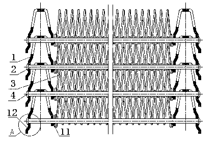
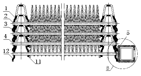
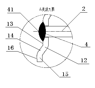
[0013] figure 1 2 is the principle of the maximum stretch state of the spiral mesh belt, 2 is the principle diagram of the minimum contraction state of the spiral mesh belt, image 3 for figure 1 Enlarged view of A, Figure 4 for figure 2 The enlarged view of B in the figure, as shown in the figure, the present invention includes that the string rod (2) is sequentially connected with the connecting plate (1), the threaded line (3) and the connecting plate (1) on the other side in sequence, and is characterized in that: The two ends of the string rod (2) are made with arc risers (4), and the arc riser (4) is fixedly connected with the string rod (2) and the connecting plate (1), and the top of the riser (41) reaches The distance from the outer end surface (13) is smaller than the distance from the outer end protruding surface (16) to the outer end surface (13); the inn...


PUM


Abstract

The invention belongs to a long-life extension-resistant threaded mesh belt. The technical scheme includes that the long-life extension-resistant threaded mesh belt comprises bunching rods (2) which are sequentially connected with joint plates (1) on one side, thread lines (3) and the joint plates (1) on the other side. The long-life extension-resistant threaded mesh belt is characterized in that arch-shaped protruding heads (4) are manufactured at two ends of the bunching rods (2) and fixedly connected with the bunching rods (2) and the joint plates (1), the distance between top portions (41) of the protruding heads and external end faces (13) is smaller than that between external protruding faces (16) and the external end faces (13), inner ends (11) of the joint plates (1) are fixedly connected with the thread lines (3), each of outer ends (12) of the joint plates (1) comprises the external end face (13), an external end folding position (14), an external protruding position (15) and the external protruding face (16), and a hub friction bar (5) is correspondingly arranged outside of each of the external protruding faces (16). The long-life extension-resistant threaded mesh belt has the advantages of firmer structure and longer service life.

Description

[0001] technical field [0002] The invention relates to a mechanical conveying device, in particular to a high-life anti-extrusion spiral mesh belt. Background technique [0003] The existing spiral conveying mesh belt has great defects and deficiencies in the structure of the connecting plate and the solder joints between the connecting plate and the string rods. Because the riveted joint and the connecting plate are only partially connected when welding the bending edge, there is no 360° fusion welding, so that the mesh belt structure is not strong enough; when the mesh belt is squeezed, the hub friction strip directly acts on the end of the string rod At the welding point of the riveting head, it is easy to cause the welding point to be squeezed and damaged. In a word, the solder joints are not strong enough and subjected to extrusion force, so that the existing mesh belt will break at the solder joints. Therefore, the service life is short, and the conveyor belt n...

Claims


Application Information

Patent Timeline
Patent Type & Authority Applications(China)
IPC IPC(8): B65G15/30
Inventor 魏德强陈忠何剑新
Owner FUJIAN SNOWMAN
Learn More