Combined building structure, installation method, house and toilet

A technology of building structure and square frame, which is applied in the direction of building components, building structure, construction, etc., and can solve the problems of time-consuming and labor-intensive installation, self-tapping screws affecting the appearance, etc.

Inactive Publication Date: 2013-04-03
柳秋香 +2
View PDF10 Cites 22 Cited by
  • Summary
  • Abstract
  • Description
  • Claims
  • Application Information

AI Technical Summary

Problems solved by technology

For the keel of this structure, the connection between the panel and the keel requires self-tapping screw connectors. The installation is time-consuming and laborious, and self-tapping screws affect the appearance

Method used


Image

  • Combined building structure, installation method, house and toilet
  • Combined building structure, installation method, house and toilet
  • Combined building structure, installation method, house and toilet

Examples


Embodiment 1

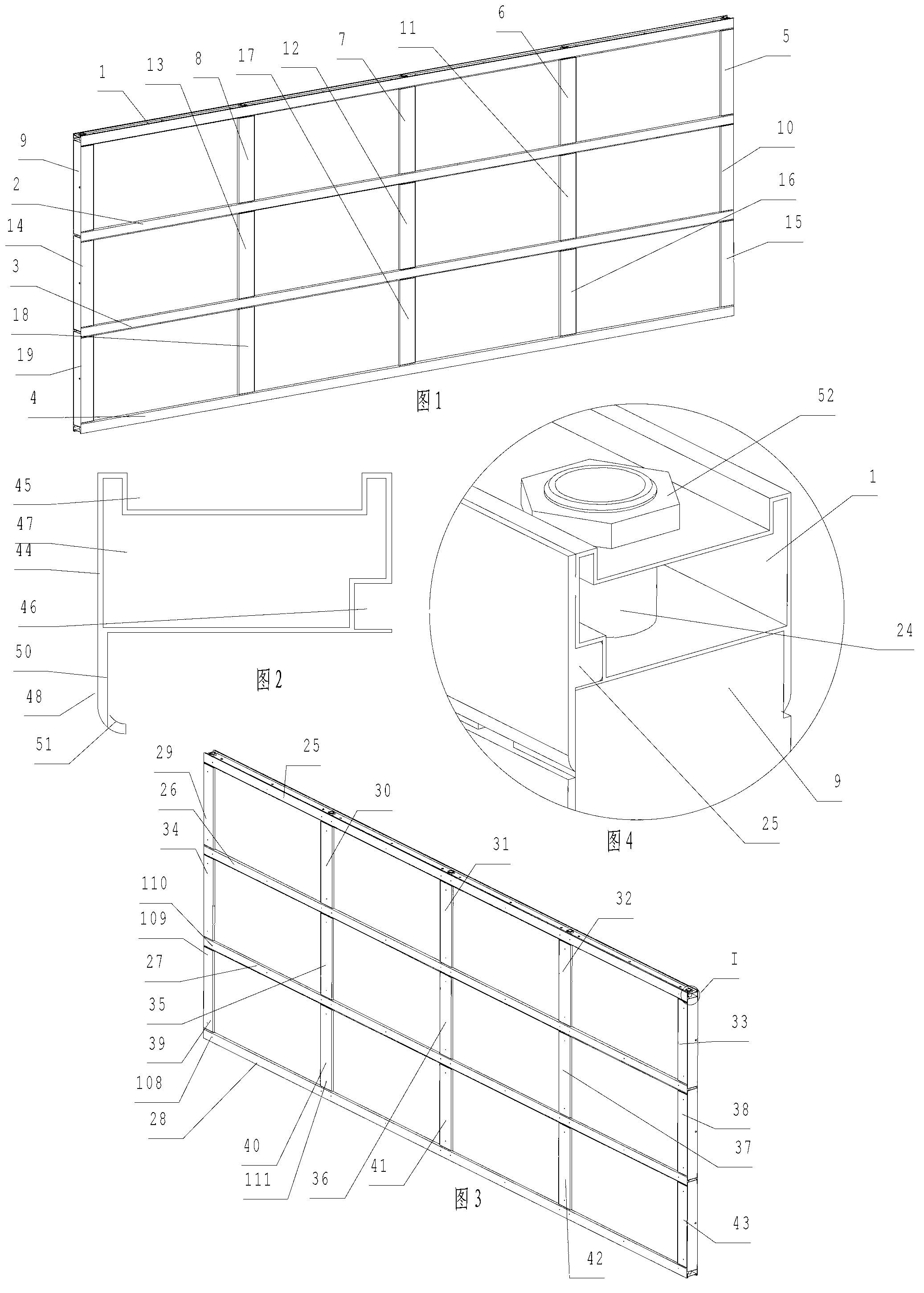
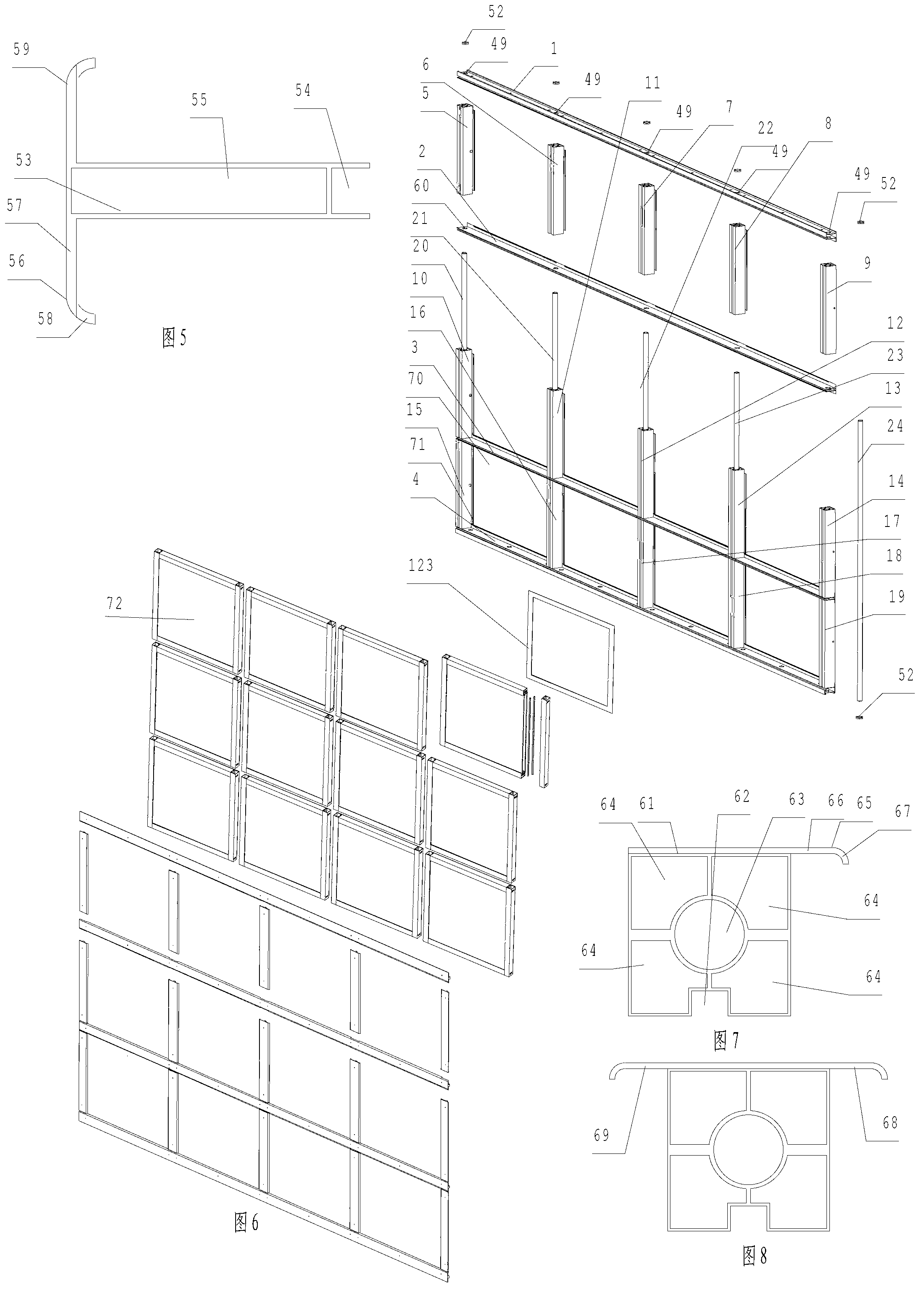
[0151] Such as figure 1 , Figure 6 As shown, a composite building structure is a composite wall structure, including a first keel 1, a first keel 2, a first keel 3, and a first keel 4 arrayed in a vertical direction from top to bottom, and the first keel 4 is installed on the first keel 1. The first keel 2 is perpendicular to the first keel 1 and the first keel 2. From the front side, the second keel 5, the second keel 6, the second keel 7, and the second keel are arranged horizontally from left to right. 8. The second keel 9 is installed between the first keel 2 and the first keel 3. It is perpendicular to the first keel 2 and the first keel 3 and is respectively located on the second keel 5, the second keel 6, the second keel 7, and the second keel. The second keel 10, the second keel 11, the second keel 12, the second keel 13, and the second keel 14 arranged horizontally directly under the keel 8 and the second keel 9 are installed between the first keel 3 and the first k...

Embodiment 2

[0169] Different from Example 1, as Figure 14 As shown, the composite building structure 140 on the left and the composite building structure 141 on the right are spliced ​​together to form a composite building structure.

[0170] Such as Figure 14 As shown, it also includes inserting into the through holes of the first keel 142, the first keel 143, the first keel 144, and the first keel 145 from the right side, similar to the cross-section of the corresponding through hole, passing through the corresponding first keel The first keel connector 146, the first keel connector 147, the first keel connector 148, and the first keel connector 149 fixed by screws (not shown), at the first keel connector 146, the first keel connector 147 , the first keel connector 148 and the first keel connector 149 are respectively provided with a third through hole 151, a third through hole 152, a third through hole 153, The third through hole 154, the lower end of the fixed shaft 150 is fixed w...

Embodiment 3

[0174] Different from Embodiment 1, there are four first keels installed vertically, and four second keels are installed horizontally between every adjacent two second keels. Such as Figure 15 , Figure 16 As shown, the rightmost first keel 180 includes a square first keel body 184, which runs through the two ends of the first keel body 184 up and down, and cooperates with the first spacer 186 to provide a resisting groove 185, and the resisting groove 185 is close to the outdoor side. The right side 188 of the groove wall is lower than the right side 189 of the groove wall near the indoor side of the resisting groove 185, and penetrates the two ends of the first keel body 184 up and down, so that the wall thickness of the first keel body 184 is relatively uniform. The hole 190 is perpendicular to the bottom surface of the first keel body 184, and the resisting strip 191 is flush with the surface of the first keel body 184 facing the outside, and four first through holes 192...


PUM


Abstract

The invention discloses a combined building structure and an installation method. The building structure comprises first keels, second keels and interlayer modules and further comprises more than two fixing shafts and locking members arranged at two ends of the fixing shafts, wherein each first keel is provided with more than two opposite side walls vertically penetrating through the first keel and first through holes matched with the fixing shaft; each second keel is only provided with a second through hole, which is matched with the fixing shaft and penetrates through two end parts of the second keel; more than two parallel second keels are arranged between every two adjacent first keels, the fixing shafts penetrate through the first through holes of the first keels, then penetrate through the second through holes of the second keels and the first through holes of the first keels in sequence more than two times, and finally are used for locking and installing the first keels and the second keels together through the locking members arranged at two ends of the fixing shafts; and the locking members are accommodated in the corresponding first keels. The combined building structure has the advantages of simple structure, simplicity and convenience for installation, reliability for fixation, good rigidity and strength and more attractive appearance.

Description

technical field [0001] The invention relates to a building structure, in particular to a combined wall, or combined window, or combined house, or combined toilet. Background technique [0002] In the utility model patent No. 94247873.8, a joint structure of a steel frame, a wall panel, a ceiling, and a roof is disclosed. Punch multiple lugs at equal intervals on the side of the profile lug bar of the steel frame. The lug strips are divided into A type and B type. One side is a vertical lug, and the other side is a horizontal lug; the panels are also divided into A-type panels and B-type panels. The side edge of the character ", the other side is the end of the word "one", and a hook cavity and hook must be set in the middle, with the side edge of the word "ji" (or "B") and the end of the word "one" on the other panel The side and the ear are socketed and meshed together, and the cycle goes round and round, and multiple panels are assembled into a whole surface, which can c...

Claims


Application Information

Patent Timeline
Patent Type & Authority Applications(China)
IPC IPC(8): E04B1/18E06B9/264
CPCE04B2/96E04B2/7809E04C2/38E06B1/366E04B2/7433E04B2001/2466E04B1/24E04B2/74E06B1/36
Inventor 杨东佐
Owner 柳秋香
Why Eureka
Try Eureka