Self drilling screw structure

A drilling screw and structure technology, which is applied in the direction of screws, connecting components, threaded fasteners, etc., can solve the problems of long drilling time, broken end, unstable attack speed and other problems of drilling screw

Inactive Publication Date: 2013-04-03
HOME REEN ENTERPRISE
View PDF7 Cites 8 Cited by
  • Summary
  • Abstract
  • Description
  • Claims
  • Application Information

AI Technical Summary

Problems solved by technology

However, when the known end-drilling screw 1 is used to drill an iron plate, the chips produced will be in the shape of long strips and wrap around the thread 122. The screw-in of the drill-tail screw 1 causes the screw-in work of the drill-tail screw 1 to take too long, and even causes the end to break

Method used


Image

  • Self drilling screw structure
  • Self drilling screw structure
  • Self drilling screw structure

Examples


Embodiment Construction

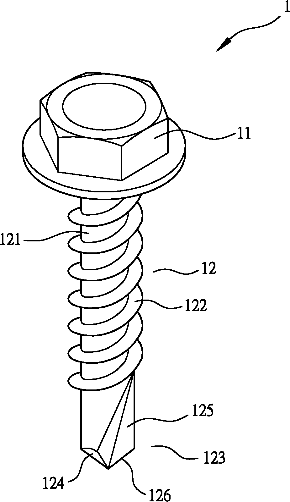
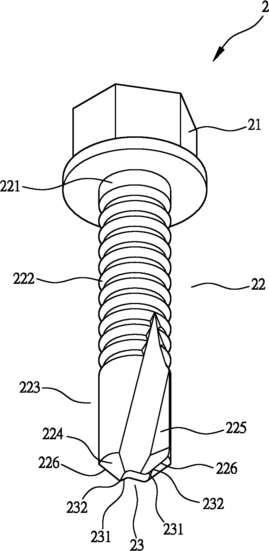
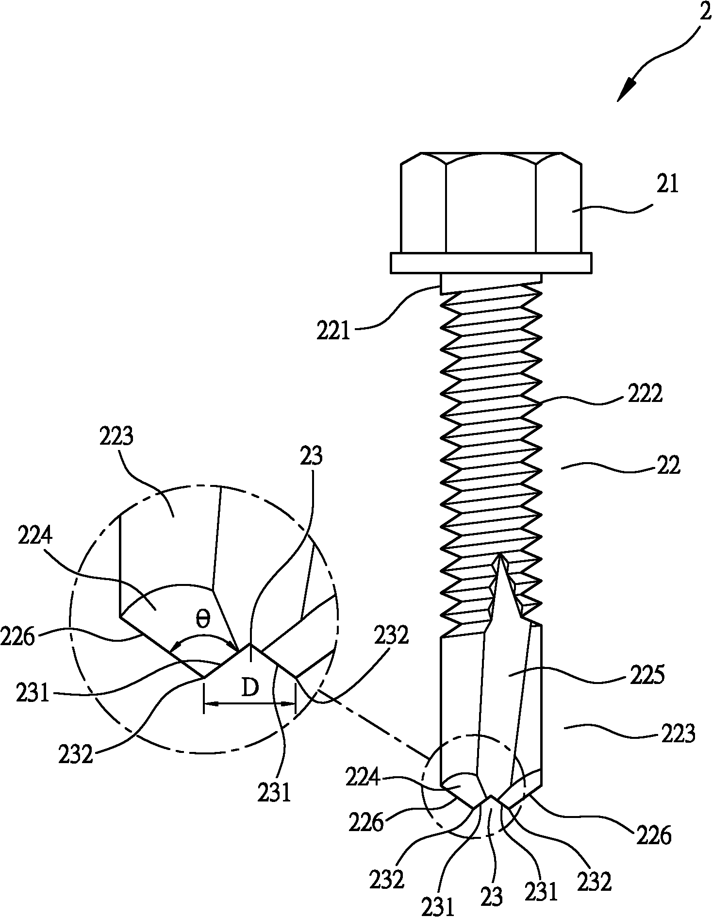
[0024] First, see figure 2 , 3 As shown, the drilling screw 2 of the present invention includes a screw head 21 and a rod body 22 arranged on the screw head 21. The peripheral surface 221 of the rod body 22 is provided with a helical thread 222, and the rod body 22 end is formed with a cylindrical drill portion 223, and the drill portion 223 is outwardly formed with a ring cone surface 224. At the same time, the drill portion 223 is provided with two chip removal grooves 225, and the chip removal groove 225 is connected with the ring cone. An outer cutting edge 226 is formed at the junction of the surfaces 224, wherein an inverted V-shaped cutting edge 23 is formed at the junction of the annular cone surface 224 and the outer cutting edge 226, and an inner cutting edge 23 is formed on both sides of the cutting edge 23. Edge 231, cutting edge 23 and outer cutting edge 226 form two sharp points 232, so that these two sharp points 232 have outer cutting edge 226 and inner cutti...


PUM


Abstract

The invention relates to a self drilling screw structure which comprises a screw head and a rod body arranged on the screw head. Spiral threads are circularly arranged on the circumferential face of the rod body and a columned drill lip is formed at the tail end of the rod body; an outward circular conical surface is formed on the drill lip; two rows of chip removal ditches are arranged on the drill lip; outer tool edges are respectively formed at the joints of the chip removal ditches and the circular conical surface; inverted V-shaped cutting edges are respectively formed at the junctions of the circular conical surface and the outer tool edges; inner tool edges are respectively formed at the two sides of the cutting edges; the inverted V-shaped cutting edges and the outer tool edges form two tip points; and in such a way, the two tip points are provided with both outer tool edges and inner tool edges. Through the outer and inner tool edges of the two tip points, the self drilling screw structure can effectively cut the chips produced in the drilling process so as to prevent the chips from winding on the threads and to improve the tapping speed. In addition, the included angle of each tip point is 15-135 degrees, and the distance between the two tip points is not more than 25% of the outer diameter of the drill lip, so the self drilling screw can have good cutting and stabilizing effects in the drilling process.

Description

technical field [0001] The invention relates to a drill tail screw structure, in particular to a drill tail screw structure which can avoid swarf winding and increase attack speed. Background technique [0002] General existing drill end screws 1, see figure 1 As shown, it includes a screw head 11, and a rod body 12 arranged on the screw head 11, wherein, the peripheral surface 121 of the rod body 12 is provided with helical thread 122, and the end of the rod body 12 is formed with a drill edge part 123, and the drill edge portion 123 is formed with a ring cone surface 124 outwards, and at the same time, the drill edge portion 123 is provided with two chip removal grooves 125, and the chip removal groove 125 is connected with the ring cone surface 124 and the rod body A cutting edge 126 is respectively formed at the joints of the peripheral surfaces 121 of 12 . [0003] When the conventional drilling screw 1 is engaged in the locking operation, the cutting edge 126 is used...

Claims


Application Information

Patent Timeline
IPC IPC(8): F16B25/04F16B25/10
Inventor 苏皇家
Owner HOME REEN ENTERPRISE
Why Eureka
Try Eureka