Signal processing during fault conditions

A fault condition, failure technique, applied in the field of signal processing during fault conditions

Inactive Publication Date: 2013-04-03
SENSATA TECHNOLOGIES INC
View PDF0 Cites 3 Cited by
  • Summary
  • Abstract
  • Description
  • Claims
  • Application Information

AI Technical Summary

Problems solved by technology

That is, the system may detect that the sensor voltage is about 0.2*Vpwr, not that an error condition occurred during sampling

Method used


Image

  • Signal processing during fault conditions
  • Signal processing during fault conditions
  • Signal processing during fault conditions

Examples


Embodiment Construction

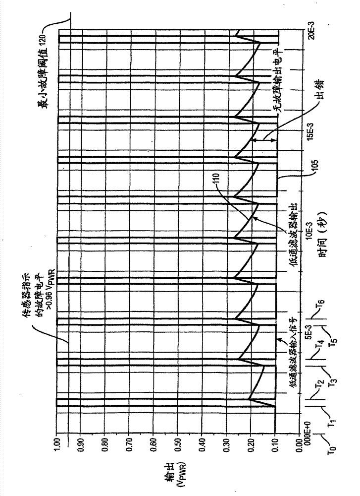
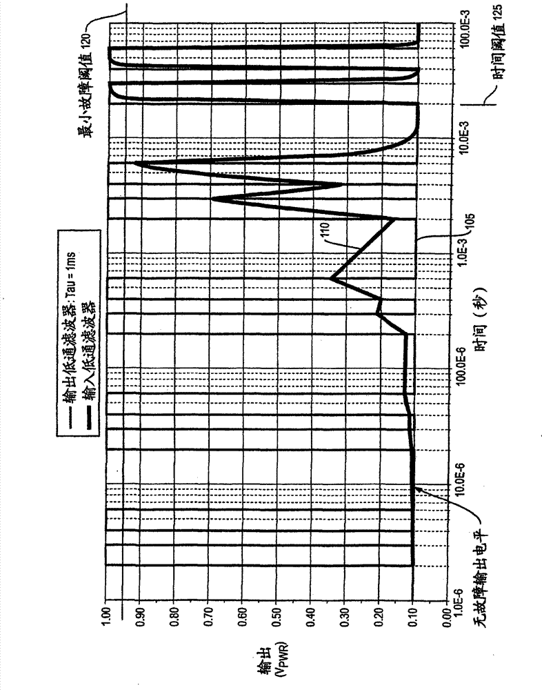
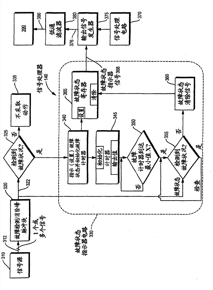
[0043] According to an embodiment herein, the system is configured to monitor received signals. In response to detecting a fault condition associated with the received signal, the system sets a fault status indicator to indicate the occurrence of the detected fault condition. The system sets the status of the fault status indicator for at least a predetermined amount of time to indicate the occurrence of a detected fault condition. This ensures that downstream resources are able to detect failures as they occur. The system again monitors signal integrity after setting the fault status indicator for at least a predetermined amount of time to indicate the occurrence of a detected fault condition. After a predetermined amount of time, in response to detecting that there is no longer a fault associated with the monitoring signal, the system changes the fault status indicator to indicate the absence of a fault condition.

[0044] image 3 is an example diagram illustrating a sys...


PUM


Abstract

The invention relates to signal processing during fault conditions. A system is configured to monitor a received signal. In response to detecting a fault condition associated with the received signal, the system sets a fault status indicator to indicate occurrence of the detected fault condition. The system sets a state of the fault status indicator for at least a predetermined amount of time to indicate occurrence of the detected fault condition. Subsequent to setting the fault status indicator for at least the predetermined amount of time to indicate the occurrence of the detected fault condition, the system monitors integrity of the signal again. After the predetermined amount of time, in response to detecting that there is no longer a fault associated with the monitored signal, the system modifies the fault status indicator to indicate absence of the fault condition.

Description

Background technique [0001] Conventional sensor devices are often used to measure environmental conditions. By means of the signal information generated by these sensor devices, it is possible to electrically monitor environmental conditions and to execute or prevent the execution of one or more functions. [0002] One conventional sensor device is a pressure transducer. For example, typically a pressure transducer produces an output signal such as a voltage that varies within an operating range with the current pressure condition detected by the sensor device. If a higher pressure is detected in the monitored area, the pressure transducer will generate an output signal indicating the higher pressure. If the current pressure detected by the sensor device in the monitored area is relatively low, the pressure transducer will adjust the output signal to indicate the lower pressure. [0003] In some cases, the amplitude of the output signal produced by the pressure transducer i...

Claims


Application Information

Patent Timeline
Patent Type & Authority Applications(China)
IPC IPC(8): G01D18/00
CPCG01D3/08G01D18/00G01L27/007
Inventor D·L·科克姆
Owner SENSATA TECHNOLOGIES INC
Why Eureka
Try Eureka