Dimming circuit and dimming method for LED light supplementing lamp

An LED fill light and dimming circuit technology, applied in the field of dimming technology, can solve the problems of inability to accurately control the luminous brightness, many components, complicated circuits, etc., and achieve accurate brightness control, high dimming precision, and peripheral device consumption. less effect

Inactive Publication Date: 2013-04-03
上海澳星照明电器制造有限公司
View PDF6 Cites 10 Cited by
  • Summary
  • Abstract
  • Description
  • Claims
  • Application Information

AI Technical Summary

Problems solved by technology

The disadvantage of this control circuit is that the MOSFET drive circuit consists of multiple triodes to form a loop, with many components and complex circuits.
[0005] The dimming method based on the above-mentioned dimming circuit realizes the stepless adjustment of brightness through the analog control method. This adjustment method controls the color temperature of the light emitted by the LED to change with the change of the LED current. The color of LED is very important, and the deficiency of this control method is particularly obvious; moreover, the existing dimming method cannot accurately control the specific amount of luminous brightness

Method used


Image

  • Dimming circuit and dimming method for LED light supplementing lamp
  • Dimming circuit and dimming method for LED light supplementing lamp

Examples


Embodiment Construction

[0024] In order to make the technical means, creative features, objectives and effects achieved by the present invention easy to understand, the present invention will be further described below in conjunction with specific illustrations.

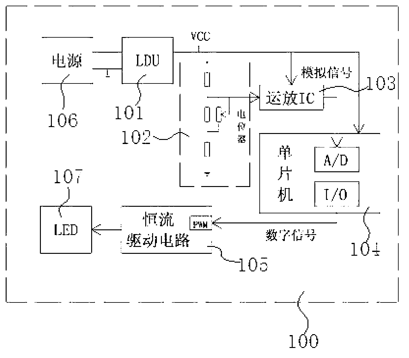
[0025] Such as figure 2 As shown, the LED fill light dimming circuit 100 provided by the present invention mainly includes an LDU module 101 , a voltage sampling circuit 102 , an amplifier 103 , a single chip microcomputer 104 and a constant current driving circuit 105 .

[0026] The LDU module 101 is a high-precision reference voltage module, which provides an accurate reference voltage for the entire circuit. Therefore, its input end is connected with the power supply 106, and its output end is respectively connected with the voltage sampling circuit 102, the amplifier 103 and the single-chip microcomputer 104 in the dimming circuit to provide them with reference voltages respectively.

[0027] The voltage sampling circuit 102 is used t...


PUM


Abstract

The invention discloses a dimming circuit and a dimming method for an LED light supplementing lamp. An input end of a reference voltage module in the dimming circuit is connected with a power source, an output end of the reference voltage module is connected with a voltage sampling circuit, an amplifier and a single chip microcomputer, an output end of the voltage sampling circuit is connected with the amplifier, an output end of the amplifier is connected with the single chip microcomputer, the single chip microcomputer is connected with a constant-current driving circuit, and the constant-current driving circuit is in drive connection with an LED. The dimming method includes steps of (1), acquiring a reference voltage source via the reference voltage module; (2), matching a potentiometer with a divider resistor to sample signals; (3), enabling an operational amplifier circuit to process the signals so as to remove interference signals; (4), enabling the single chip microcomputer to complete high-precision A/D (analog/digital) conversion to obtain digital signals; (5), processing the digital signals to obtain digital PWM (pulse-width modulation) signals; and (6), adjusting the constant-current driving circuit by the digital PWM signals to control brightness variation of the LED. According to the dimming scheme, the dimming circuit and the dimming method have the advantages of high dimming precision, accurate brightness control, few required peripheral devices and the like.

Description

technical field [0001] The invention relates to an LED supplementary light technology, in particular to a dimming technology in an LED supplementary light. Background technique [0002] The dimming control of LED supplementary light series products currently uses analog control to realize stepless adjustment of brightness. The specific principle of dimming is as follows: figure 1 shown. [0003] according to figure 1 It can be seen that the dimming circuit of the existing LED supplementary light mainly includes a voltage adopting circuit 1, an amplifier 2 formed by an operational amplifier IC, and a MOSFET drive circuit 3, wherein the voltage adopting circuit 1 is connected to the power supply 4, and its output terminal is connected to the amplifier 2 Connected, the amplifier 2 is connected to the MOSFET drive circuit 3, and then the MOSFET drive circuit 3 is driven to connect to the LED5. [0004] The dimming circuit samples and feeds back the supply current of the LED b...

Claims


Application Information

Patent Timeline
Patent Type & Authority Applications(China)
IPC IPC(8): H05B37/02
Inventor 曹金韡叶星陈俊宏
Owner 上海澳星照明电器制造有限公司
Why Eureka
Try Eureka