
Ejecting device for a movable furniture part

A technology for pushing out devices and furniture parts, applied in furniture parts, wing fan parts, household appliances, etc., to achieve the effects of compact structure, overload prevention, and simple detection

Active Publication Date: 2013-04-03
JULIUS BLUM GMBH
View PDF8 Cites 2 Cited by
  • Summary
  • Abstract
  • Description
  • Claims
  • Application Information

AI Technical Summary

Problems solved by technology

The disadvantage here is that the energy accumulator required for detection is located in the ejector rod itself, the detectability is thus dependent on the shape of said ejector rod

Method used


Image

  • Ejecting device for a movable furniture part
  • Ejecting device for a movable furniture part
  • Ejecting device for a movable furniture part

Examples


Embodiment Construction

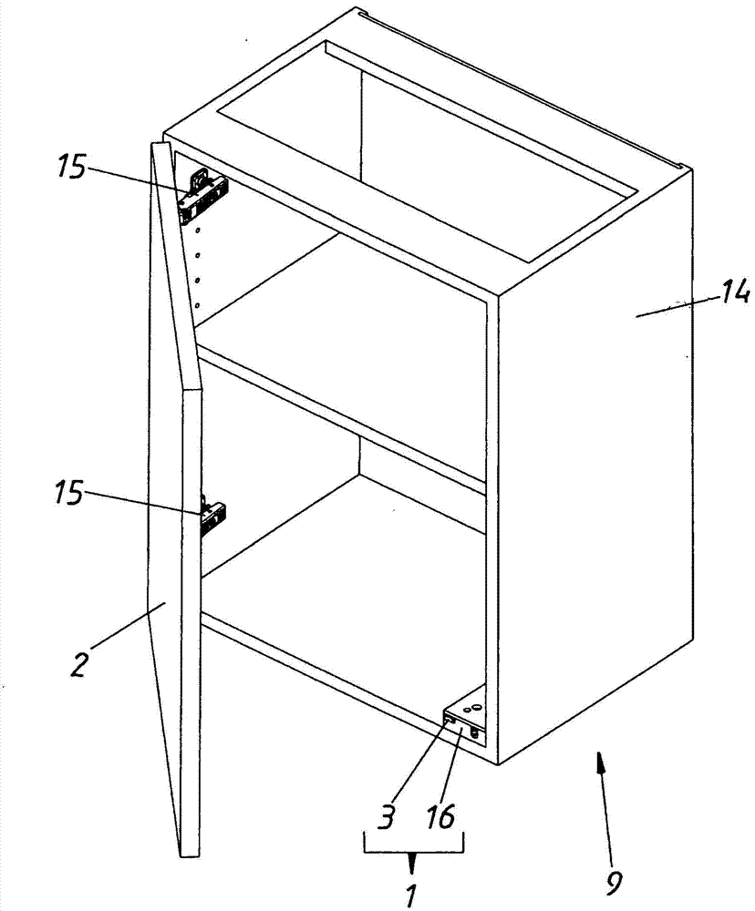
[0036] figure 1 A piece of furniture 9 is shown, comprising a furniture body 14 and a movable furniture part 2 , which is fastened movably to the furniture body 14 by means of two hinges 15 . The ejection device 1 is arranged on the lower right corner of the furniture body 14 , wherein in this figure in particular the housing 16 and the ejector 3 can be seen in the retracted first position of the ejection device.

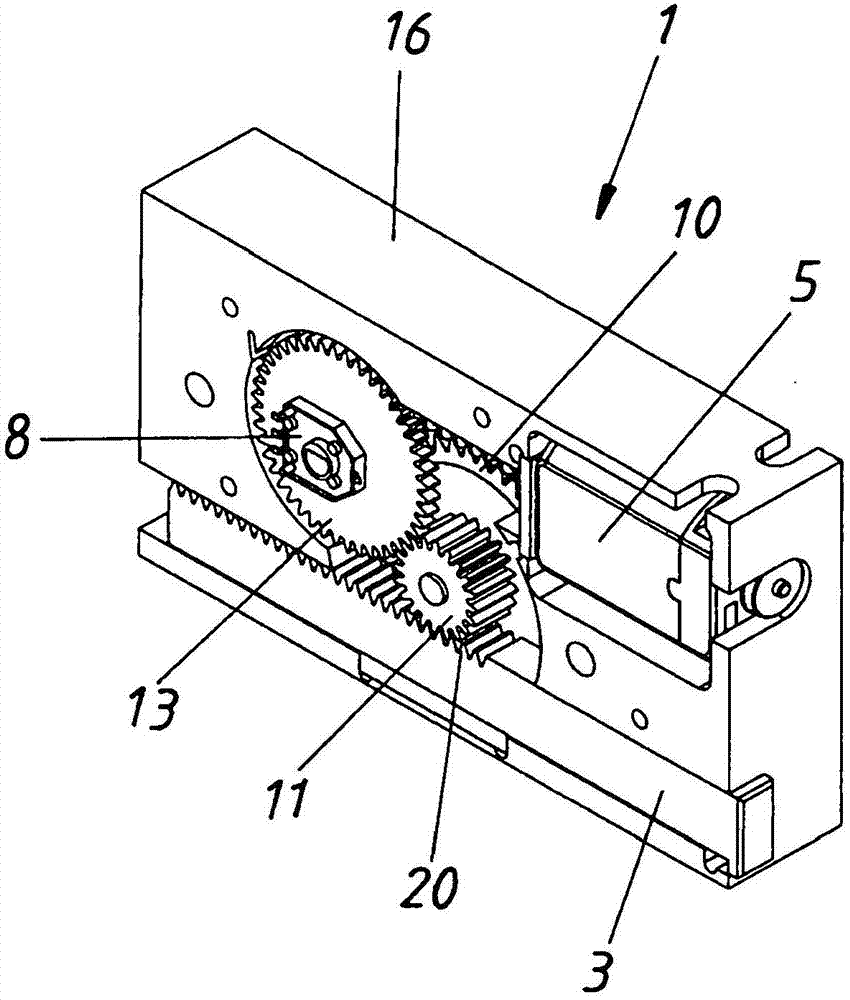
[0037] figure 2 The ejector device 1 is shown in the first retracted position of the ejector 3 . In this exemplary embodiment of the invention, the ejector 3 is formed in one piece with the output 20 of the transmission 19 . The monitoring device 8 is formed here as a potentiometer, which is coupled to the transmission part 11 by means of a monitoring gear 13 .

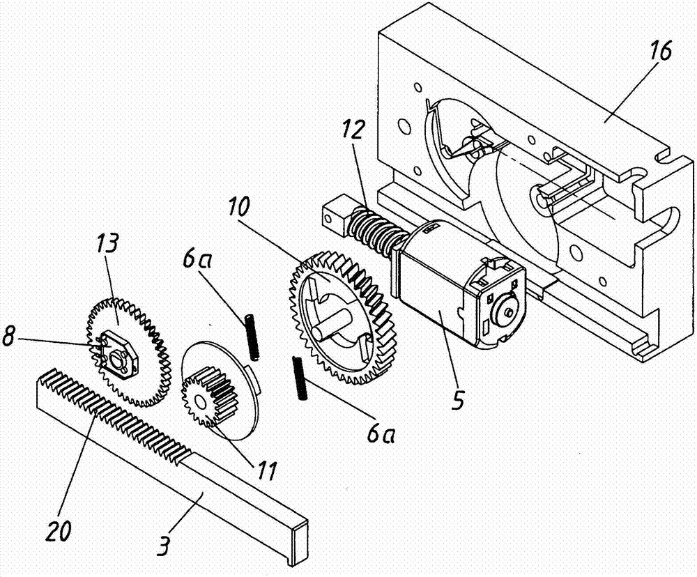
[0038] image 3An exploded view of the push-out device 1 is shown, which includes a housing 16; an electric drive unit 5; a worm 12 connected to the drive shaft of the drive unit 5; a first gear 10; a...


PUM


Abstract

The invention relates to an ejecting device (1) for a movable furniture part (2), in particular a door or drawer, comprising an ejector (3), which can be moved between a first (Fig. 4) and a second position (Fig. 5), for ejecting the movable furniture part (2), a drive train (4) having an electrical drive unit (5) that drives the ejector (3) and a gear mechanism (19) that is arranged between the drive unit (5) and the ejector (3) and that has an output (20) that acts on the ejector (3), and an open-loop or closed-loop control device (7) for controlling the drive unit (5) in an open-loop or closed-loop manner, wherein a force accumulator (6) is integrated in the gear mechanism (19) between the drive unit (5) and the output (20), a monitoring device (8) connected to the drive train (4) can detect an unloading of the force accumulator (6); and report said unloading to the open-loop or closed-loop control device (7), and the open-loop or closed-loop control device (7) activates the electrical drive unit (5) in order to move the ejector (3) back to the first position (Fig. 4) after the unloading of the force accumulator (6) has been detected.

Description

technical field [0001] The invention relates to an ejection device for a movable furniture part, in particular for a door or a drawer, comprising an ejector for ejecting a movable furniture part, the ejector being in a first position and a second position movable between them; a drive train with an electric drive unit driving the ejector and a transmission mechanism arranged between the drive unit and the ejector with a driven device acting on the ejector ; and a control or regulation device for controlling or regulating the drive unit. Background technique [0002] Electrically driven ejectors are already known. For example, AT007158U1 describes an ejector for movable furniture parts, in which the drive unit can be activated by exerting tension and / or pressure on the ejection device. In a special embodiment, the ejector has two parts that are telescopically arranged alternately, after the end of the ejection process, the movement of the movable furniture part away from th...

Claims


Application Information

Patent Timeline
Patent Type & Authority Applications(China)
IPC IPC(8): A47B88/04
CPCA47B88/0414E05Y2900/20E05F15/121E05F15/614A47B88/457
Inventor W·伯勒
Owner JULIUS BLUM GMBH
Learn More