
Linkage thrust clamping device

A clamping device and thrust technology, applied in the field of linkage thrust clamping device, can solve the problems of complex structure, high cost and high processing cost of the device, and achieve the effects of cost reduction, convenient operation and simple structure

Inactive Publication Date: 2013-04-10
CHONGQING ZHIRUIDE TECH
View PDF0 Cites 0 Cited by
  • Summary
  • Abstract
  • Description
  • Claims
  • Application Information

AI Technical Summary

Problems solved by technology

In order to follow the principle of economy and rationality, there is a certain difference in the choice of clamping device for power source mechanism between large and medium-sized workpieces and small workpieces. For large and medium-sized workpieces, pneumatic, hydraulic, electric, and electromagnetic power sources are generally used. These are suitable for small workpieces. Said too much overkill, resulting in high processing costs
Common clamping devices have the following disadvantages: 1. Using pneumatic, hydraulic, electric, electromagnetic power sources, the cost is relatively high; 2. The structure of the device is complicated, and it is inconvenient to install, disassemble and operate

Method used


Image

  • Linkage thrust clamping device

Examples


Embodiment Construction

[0011] Below in conjunction with accompanying drawing, technical scheme of the present invention is further described:

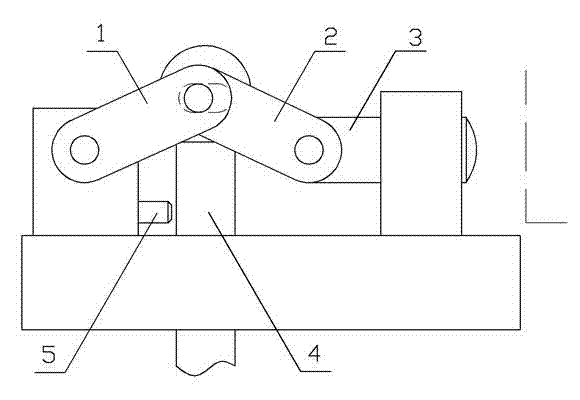
[0012] Such as figure 1 As shown in Figure 2, the present invention provides a linkage thrust clamping device, which includes a clamp body, a push rod 3 for pressing the workpiece surface, a driving rod 1 as a force applying device, a driven rod 2, and a guide rod 4, Wherein, the upper end of the guide rod 4 is provided with a terminal, and the terminal is provided with a transverse strip hole, one end of the push rod 3 is slidingly matched with the fixture body, the other end is hinged with one end of the driven rod 2, and the other end of the driven rod 2 is connected with the driving rod. One end of 1 is hinged in the horizontal strip hole, and the other end of the driving rod 1 is hinged with the fixture body. The driving rod 1 and the driven rod 2 have freedom of movement up and down under the constraint of the guide rod 4.

[0013] Specifically, the m...


PUM


Abstract

The invention relates to a clamping device, in particular to a linkage thrust clamping device, which comprises a clamp body, an ejection rod, a driving rod, a driven rod and a guide rod, wherein the ejection rod is used for pressing the surface of a workpiece, the driving rod and the driven rod are used as force applying devices, the upper end of the guide rod is provided with an end head, the end head is provided with a transverse strip hole, one end of the ejection rod is in sliding fit with the clamp body, the other end of the ejection rod is hinged with one end of the driven rod, the other end of the driven rod and one end of the driving rod are hinged in the transverse strip hole, and the other end of the driving rod is hinged with the clamp body. The linkage thrust clamping device with the technical scheme has the advantages that the structure is simple, the operation is convenient, and the cost is low.

Description

technical field [0001] The invention relates to a clamping device, in particular to a linkage thrust clamping device. Background technique [0002] In the process of mechanical processing, the positioning, clamping and position locking of the parts to be processed are essential links. The positioning of the workpiece can ensure the accuracy of processing, and the clamping can prevent accidents caused by parts flying out during processing. Locking can Ensure that the device operates within a certain range during processing. In order to follow the principle of economy and rationality, there is a certain difference in the choice of clamping device for power source mechanism between large and medium-sized workpieces and small workpieces. For large and medium-sized workpieces, pneumatic, hydraulic, electric, and electromagnetic power sources are generally used. These are suitable for small workpieces. Said too much overkill, resulting in high processing costs. Common clamping ...

Claims


Application Information

Patent Timeline
IPC IPC(8): B23Q3/00
Inventor 严米琪
Owner CHONGQING ZHIRUIDE TECH
Learn More