Stamping mechanism of automatic stamping machine

A technology of automatic stamping machine and sliding platform, applied in printing, stamping and other directions, can solve the problems of inability to meet user needs, single stamping action, etc., to achieve the effect of high stamping efficiency, efficient work, and resource saving

Inactive Publication Date: 2013-04-10
GUANGDONG UNIV OF TECH
View PDF8 Cites 13 Cited by
  • Summary
  • Abstract
  • Description
  • Claims
  • Application Information

AI Technical Summary

Problems solved by technology

[0003] Most of the existing automatic stamping machine mechanisms adopt the structure of vertical movement to achieve the purpose of stamping, and the existing closed stamping machines cannot be used for stamping documents of various sizes
In addition, the existing stamping machines generally do not have a stamp changing mechanism, only a single stamping action can be realized, which cannot meet the needs of users

Method used


Image

  • Stamping mechanism of automatic stamping machine
  • Stamping mechanism of automatic stamping machine
  • Stamping mechanism of automatic stamping machine

Examples


Embodiment

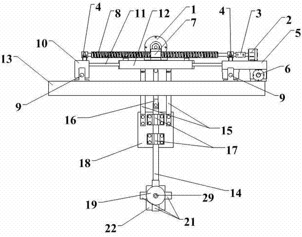
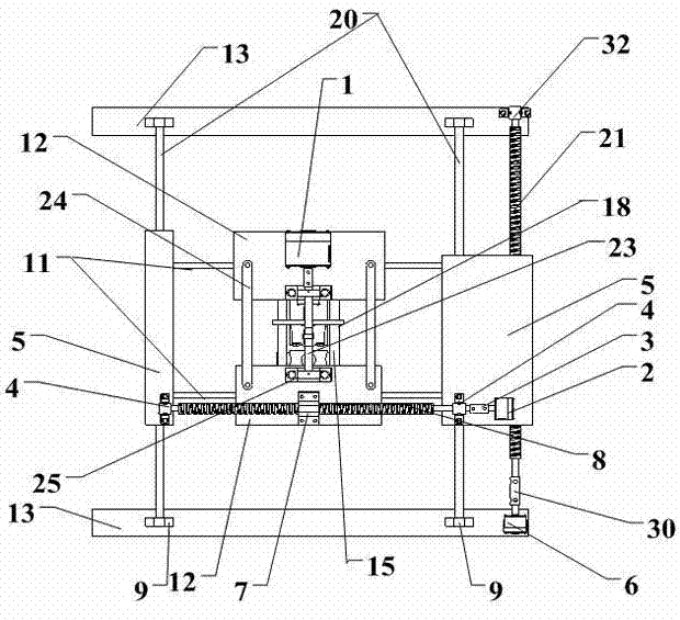
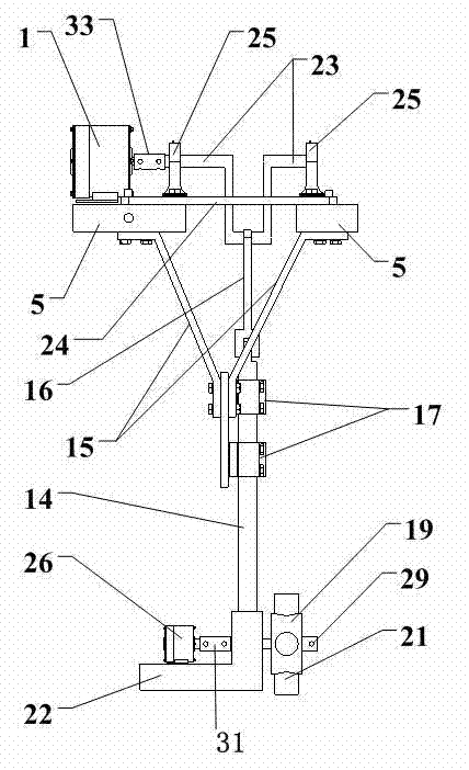
[0018] The structure diagram of the present invention is as figure 1 , 2 , 3, 4, and 5, the stamping mechanism of the automatic stamping machine of the present invention includes a first motor 1, a second motor 2, a first support 5, a third motor 6, and the first ball screw pair 7 , the first lead screw 8, the second support 10, the first slide bar 11, the third support 12, the fourth support 13, the second slide bar 14, the rib support 15, the connecting rod 16, the fixed plate 18, the turntable 19, The third slide bar 20, the second leading screw 21, the crankshaft 23, the link rod 24, the fourth motor 26, the second ball screw pair 27, the seal fixture 28, the connecting shaft 29, the fourth support 13 is fixed on the stamping machine On the casing, two third slide bars 20 in the Y direction are fixed on the fourth bracket 13, and the sliding platform composed of the first bracket 5 and the first slide bar 11 is mounted on the third slide through the sliding bearing mounte...


PUM


Abstract

The invention discloses a stamping mechanism of an automatic stamping machine, and the stamping mechanism comprises a first motor, a second motor, a first support, a third motor, a first ball bearing lead screw pair, a first lead screw, a second support, a first slide rod, a third support, a fourth support, a second slide rod, a plate rib support, a connecting rod, a fixed plate, a turntable, a third slide rod, a second lead screw, a crankshaft, a connecting frame rod, a fourth motor, a second ball bearing lead screw pair, a stamp clamp and a connecting shaft. According to the stamping mechanism of the automatic stamping machine, because the lead screw is driven to rotate by a motor lead screw, so that the support with the ball bearing lead screw pair is driven to slide on the slide rod, the stamping mechanism which is arranged on the support realizes a structure which moves at any position on a plane and a stamping position is precisely selected. In addition, the motor drives the crankshaft to rotate, the crankshaft drives the connecting rod to move, so that the slide rod is driven to slide on a slide bearing which is fixedly arranged on the fixed plate, and the stamp is driven to move up and down. Moreover, the motor drives the turntable to move through the connecting shaft, so as to select different stamps which are arranged on the turntable.

Description

technical field [0001] The invention relates to a stamping mechanism of an automatic stamping machine, which belongs to the transformation technology of the stamping mechanism of the automatic stamping machine. Background technique [0002] Seals are widely used in various occasions. For the safety of the use of the seal, the closed stamping machine is undoubtedly the most effective in protecting the seal, but the closed stamping machine has a great influence on whether the positioning of the stamping position of a document is correct. Therefore, it is very necessary that the stamping mechanism can move arbitrarily in the X-Y plane. In addition, different departments in the existing office system basically have to manage a seal. Therefore, the existing office system needs a stamping machine that can replace multiple seals and has monitoring functions to meet the requirements of efficient office work and resource saving. [0003] Most of the existing automatic sealing machin...

Claims


Application Information

Patent Timeline
Patent Type & Authority Applications(China)
IPC IPC(8): B41K3/02B41K3/62
Inventor 王晗陈新度朱自明刘强张志辉房飞宇何若涛何汉星黄静洁林文贤罗迪邹星家刘冠峰杜雪
Owner GUANGDONG UNIV OF TECH
Why Eureka
Try Eureka