
a shaft sleeve

A technology of shaft sleeves and cylinders, applied in the direction of bearing components, shafts and bearings, mechanical equipment, etc., can solve the problems of inconvenient fastening installation, increase of installation size and weight, poor coaxiality, etc., to increase feedback function, overcome Effect of adding weight and reducing product weight

Active Publication Date: 2016-02-24
JINCHENG NANJING ELECTROMECHANICAL HYDRAULIC PRESSURE ENG RES CENT AVIATION IND OF CHINA
View PDF8 Cites 0 Cited by
  • Summary
  • Abstract
  • Description
  • Claims
  • Application Information

AI Technical Summary

Problems solved by technology

[0002] When the slope is rotated and positioned, it is necessary to install a lead-out shaft, the installation space is limited, and it is not easy to fasten the installation
For this reason, the shell can only be refitted, but this increases the difficulty and cost of installation, and the centering positioning is not accurate, which easily leads to poor coaxiality and high scrap rate
At the same time, the size and weight of the installation are increased, and the reliability of the installation is reduced

Method used


Image

  • a shaft sleeve
  • a shaft sleeve
  • a shaft sleeve

Examples


Embodiment Construction

[0014] In order to better illustrate the present invention, it will be described in detail below in conjunction with the accompanying drawings.

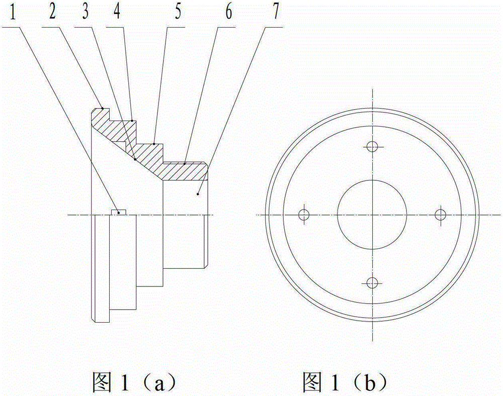
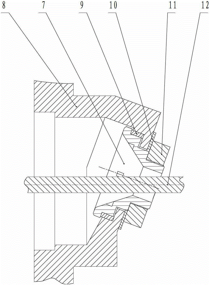
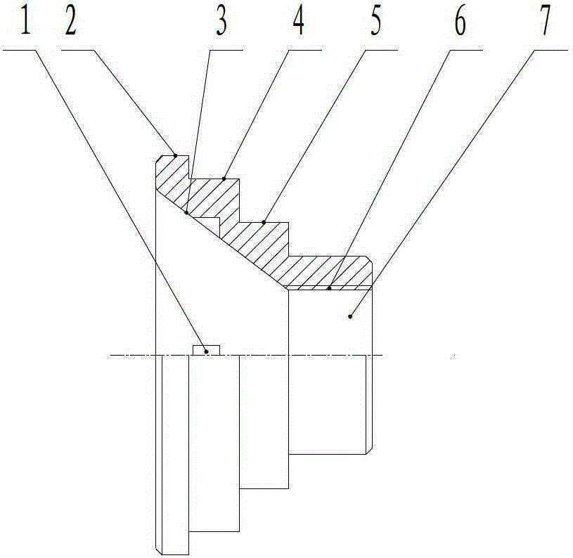
[0015] Please refer to Figure 1~ figure 2 , which is the first structural diagram and structural implementation of the bushing of the present invention.

[0016] A shaft sleeve includes a cone part and a cylinder part. The hollow cone part is provided with a flange surface 2, a positioning shoulder 4 and a matching shoulder 5. The inner surface of the hollow cone is a cone surface, and the inner surface is provided with a tightening The direction of the pin hole 1 and the fixing pin hole 1 are parallel to the axis of the cone, and the cylindrical part cooperates with the housing 8. In this embodiment, the thread 6 is located on the outer surface of the cylindrical part. The shaft sleeve 7 is installed in an inclined plane housing 8, and is positioned by the flange surface 2 and the positioning sleeve 9. When installing, insert the c...


PUM


Abstract

The invention belongs to the field of mechanical transmission, and relates to a shaft sleeve which comprises a cone part and a cylinder part, wherein the hollow cone part is provided with a flange face (2), a positioning shoulder (4) and a matching shoulder (5), and a set pin hole (1) is formed in the internal surface of a hollow cone. The shaft sleeve is convenient and quick to process, overcomes the defects of additional weight, complicated mounting, high coaxial difficulty, low mounting efficiency, and the like arising from the traditional structure, and solves the technical problem that a rotary positioning shaft sleeve mounted on an oblique plane requires stretching out of a feedback rotating shaft; the product weight is reduced; a rotary shaft feedback function is added; and the shaft sleeve plays an important role in the aspect that a rotary accessory on the oblique plane requires leading out of the rotary feedback shaft.

Description

technical field [0001] The invention belongs to the field of mechanical transmission and relates to a shaft sleeve. Background technique [0002] When the inclined plane is rotated and positioned, a lead-out shaft needs to be installed, and the installation space is limited, which is not convenient for fastening installation. For this reason, the casing can only be refitted, but this increases the difficulty and cost of installation, and the centering positioning is not accurate, which easily leads to poor coaxiality and high scrap rate. At the same time, the size and weight of the installation are increased, and the reliability of the installation is reduced. Contents of the invention [0003] The purpose of the present invention is to provide a shaft sleeve with accurate centering and positioning, quick and reliable installation, low cost, and the ability to lead out the feedback rotating shaft. [0004] The technical solution of the present invention is: a shaft sleev...

Claims


Application Information

Patent Timeline
Patent Type & Authority Patents(China)
IPC IPC(8): F16C33/04
Inventor 肖息陈焕明雷体高孟利华
Owner JINCHENG NANJING ELECTROMECHANICAL HYDRAULIC PRESSURE ENG RES CENT AVIATION IND OF CHINA
Learn More