Heat dissipation method and structure of an array LED light source panel

A technology of LED light source and heat dissipation method, which is applied in the direction of light source, plane light source, point light source, etc., can solve the problems of increasing panel production cost and complicated process, and achieve uneven heat distribution, prolong service life, and reduce temperature rise Effect

Active Publication Date: 2015-10-14
XIAMEN HUALIAN ELECTRONICS CO LTD
View PDF5 Cites 0 Cited by
  • Summary
  • Abstract
  • Description
  • Claims
  • Application Information

AI Technical Summary

Problems solved by technology

The above solution achieves the effect of uniform temperature rise across the array panel by cooling each LED through the cooling chip, which increases the production cost of the panel, and the process is more complicated

Method used


Image

  • Heat dissipation method and structure of an array LED light source panel
  • Heat dissipation method and structure of an array LED light source panel
  • Heat dissipation method and structure of an array LED light source panel

Examples


Embodiment

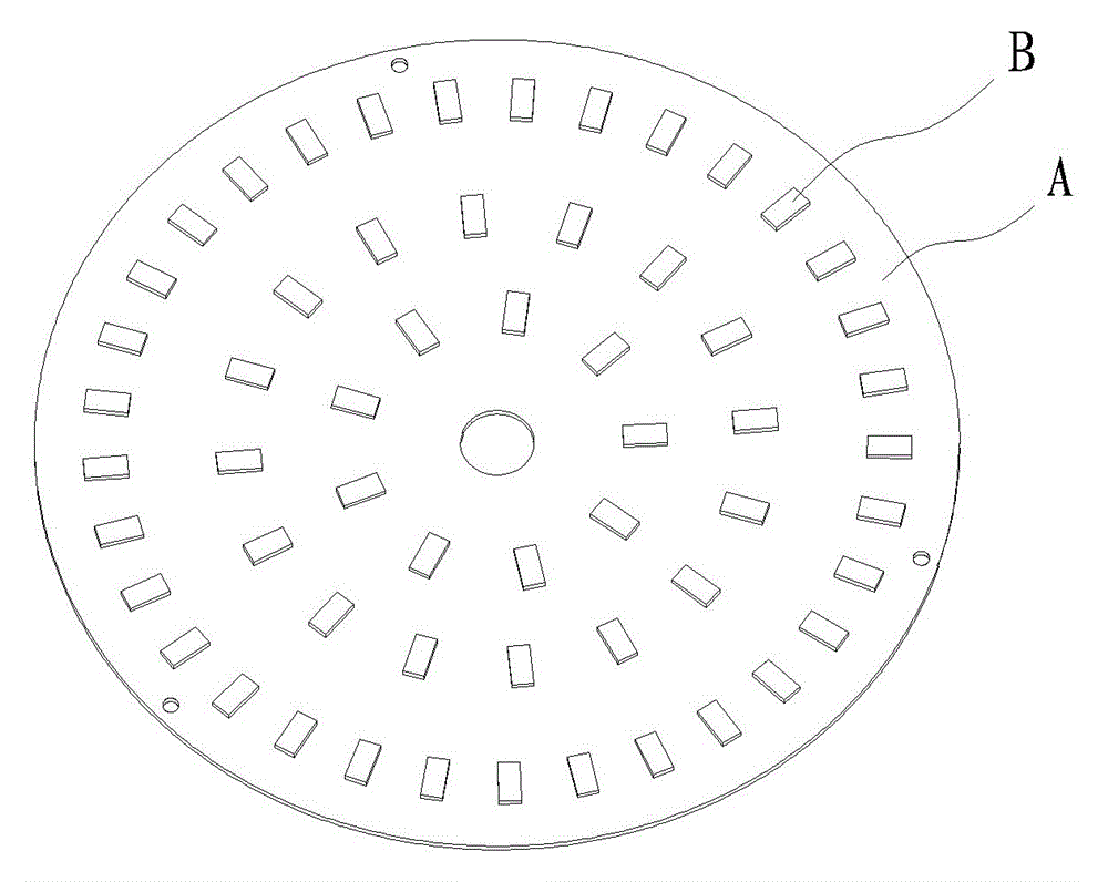
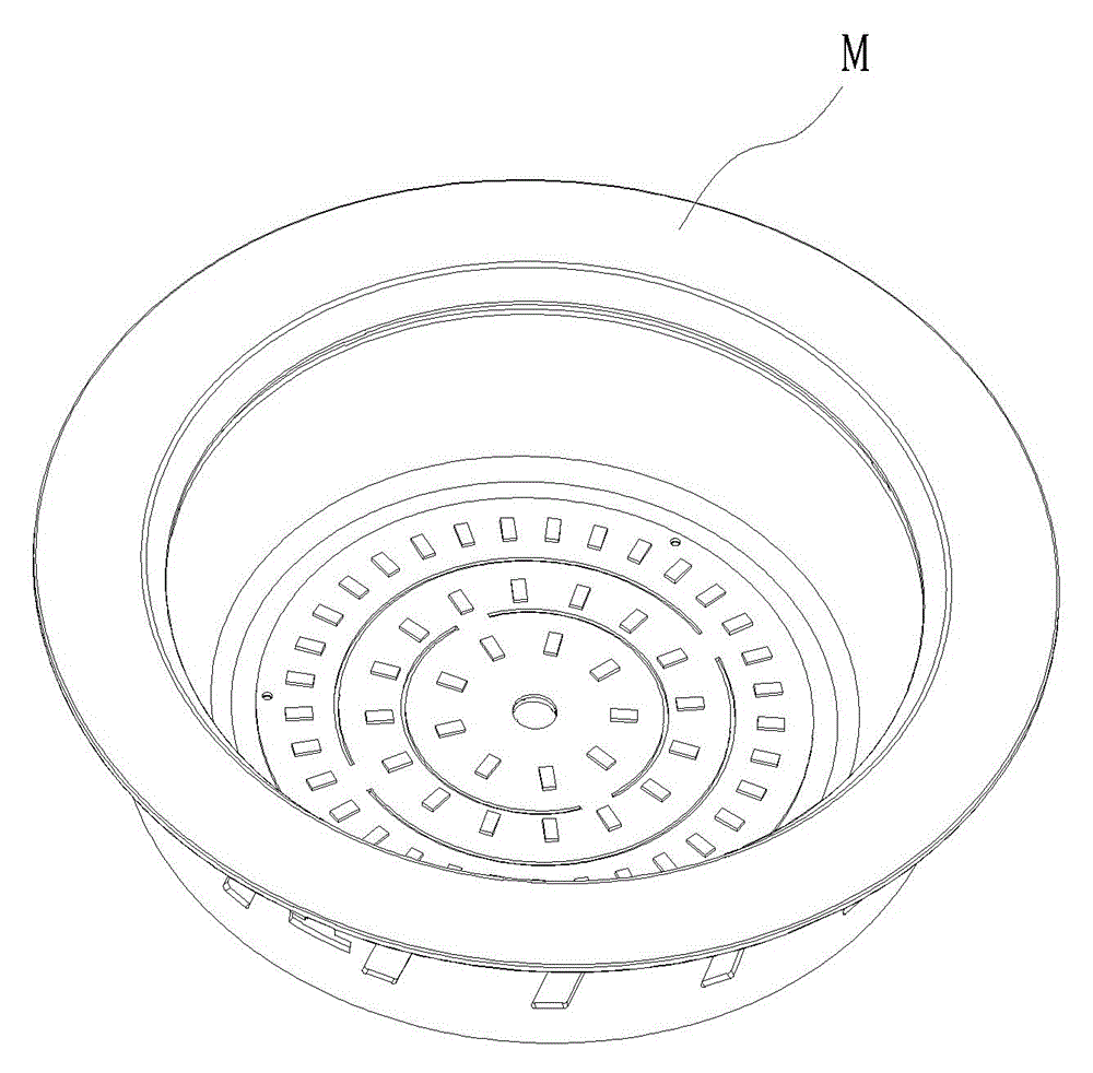
[0022] Example: see image 3 , Figure 4 or Figure 5 , A heat dissipation method for an array LED light source panel. A number of LEDs are provided on the light source panel 1 to form an LED ring with two or more arrays along the center and outwards. The heat dissipation panel 1 is provided between the adjacent inner and outer LED rings. In the matched heat insulation groove 3, each LED and the corresponding heat insulation groove form a heat dissipation channel so that heat can be quickly transferred to the back of the panel. The light source panel 1 is a printed board such as an aluminum substrate with a circular shape as a whole. image 3 , The LEDs on it are distributed in a circular array with the center of the substrate mounting hole as the center, the heat insulation grooves between adjacent LED rings are arranged at the above center, and the corresponding heat dissipation area of ​​each LED is the same. The light source panel 1 may also be a printed board such as an alu...


PUM


Abstract

The invention discloses a radiating method of an array LED (Light Emitting Diode) light source panel and a structure. Insulating grooves are formed in the LED light source panel, so that the maximum temperature of each LED particle and difference in temperature in the particles are decreased; heat in a radiating channel corresponding to each LED is transferred to the back side of the panel; the insulating grooves are distributed based on nearly same radiating area corresponding to each LED; and the difference in temperatures between the LED particles on the edge and the LED particles in the center of the panel is reduced. According to the invention, nonuniform heat distribution of the current array LED light source panel can be effectively solved, so that the service life of the whole surface light source is prolonged.

Description

technical field [0001] The invention discloses a heat dissipation method and structure of an array LED light source panel, belongs to the technical field of LED surface light source manufacturing according to the International Patent Classification (IPC), and is applicable to circular and square flat surface light sources or arc-shaped surface light sources. Background technique [0002] At present, the light source part of LED lights or lamps often adopts a combination of several LED particle arrays, which are widely used in street lights, tunnel lights, downlights, spotlights, displays and other related occasions. The problem of heat dissipation is one of the important issues encountered by LED designers, especially for the array LED light source panel formed by the combination of several LED particles, the life of each LED is related to its temperature rise, and the LED particle with the shortest life is easily damaged. It is easy to cause the entire LED surface light sou...

Claims


Application Information

Patent Timeline
Patent Type & Authority Patents(China)
IPC IPC(8): F21V29/83F21Y101/02F21V29/50F21Y105/18F21Y115/10
Inventor 陈杰曾梅真王阳夏张卫陈亚树
Owner XIAMEN HUALIAN ELECTRONICS CO LTD
Why Eureka
Try Eureka