Electronic device

An electronic device and mounting frame technology, which is applied to lighting devices, components of lighting devices, and parts of cabinets, cabinets, and drawers, etc., can solve the problems of inconspicuous indication effect and small light-emitting area, and achieve the indication effect. Visible, enlarged luminous area effect

Inactive Publication Date: 2013-04-10
HONG FU JIN PRECISION IND WUHAN CO LTD +1
View PDF2 Cites 5 Cited by
  • Summary
  • Abstract
  • Description
  • Claims
  • Application Information

AI Technical Summary

Problems solved by technology

However, the light emitted by the traditional power indicator light can only radiate toward the front side of the panel, the light-emitting area is small, and the indication effect is not obvious

Method used


Image

  • Electronic device
  • Electronic device
  • Electronic device

Examples


Embodiment Construction

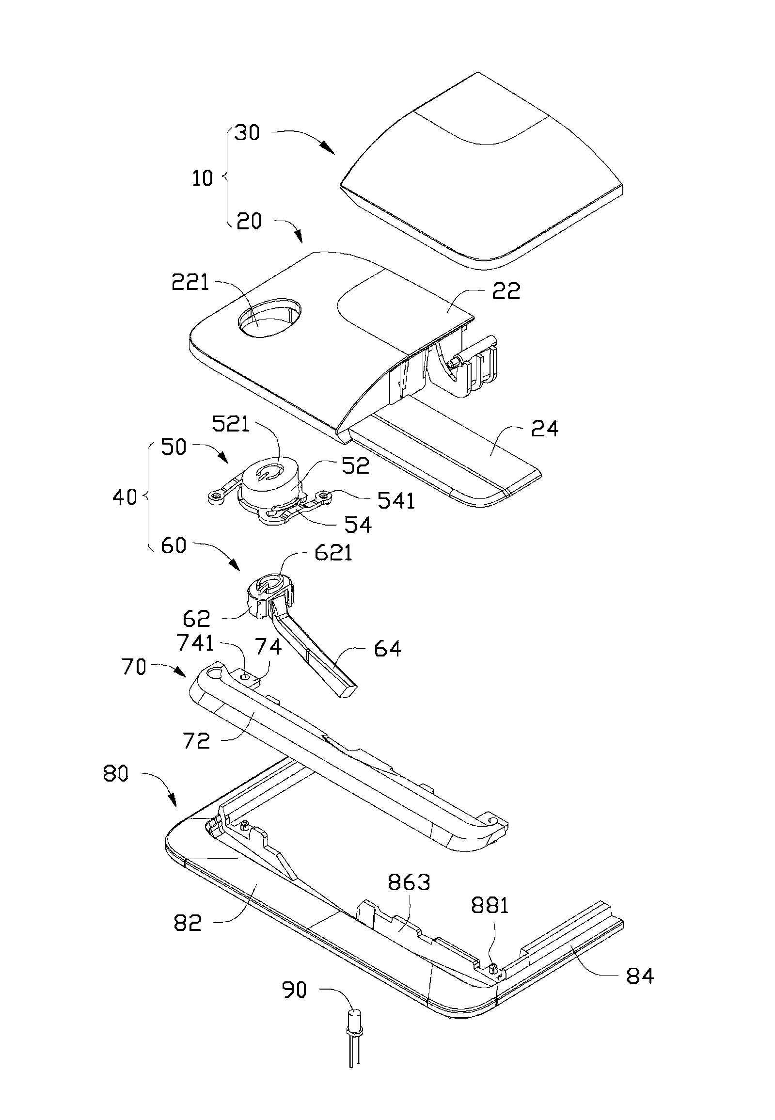
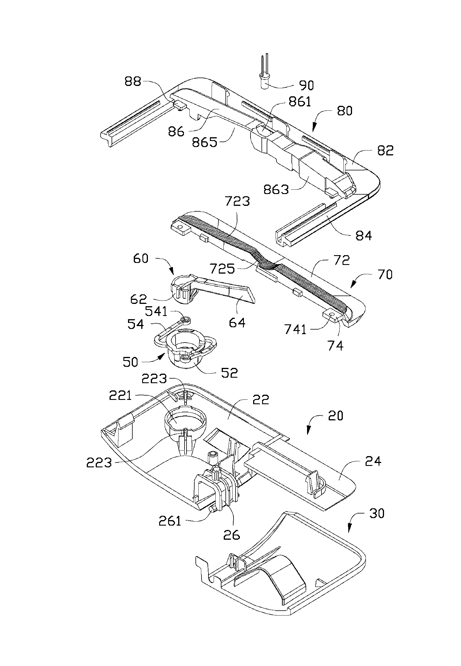
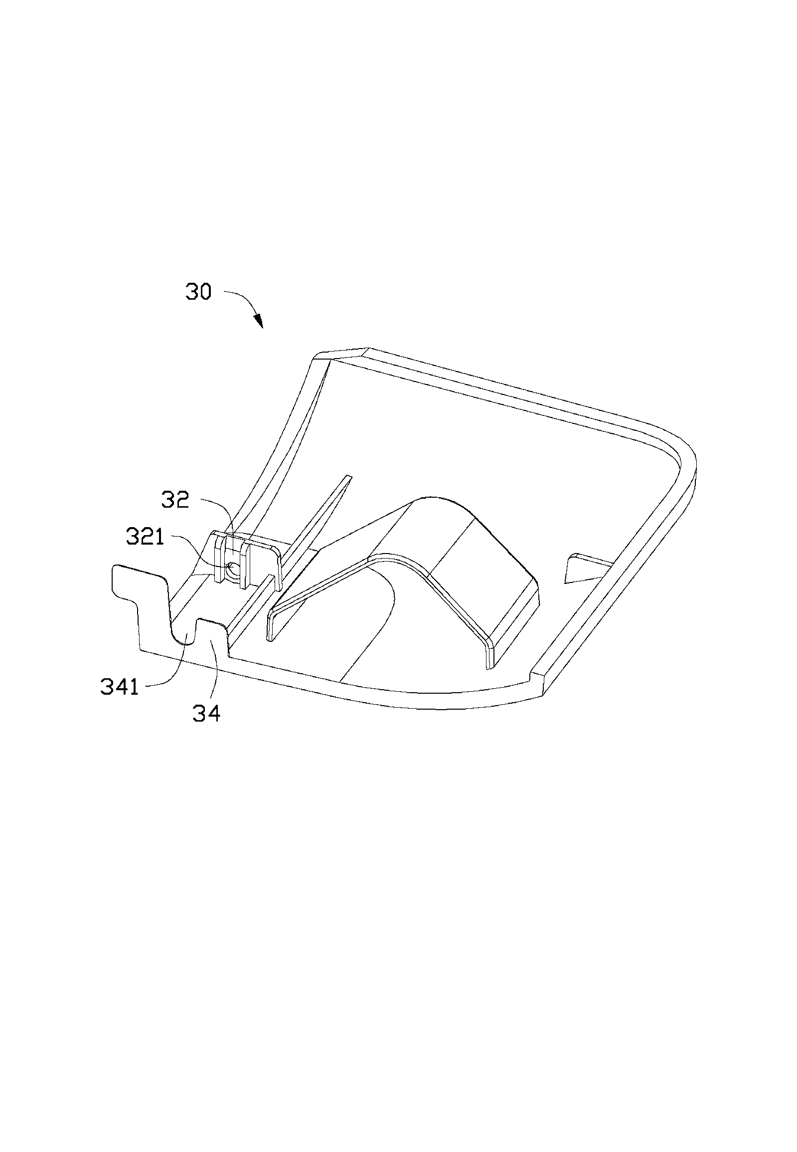
[0014] see Figure 1 to Figure 3 A preferred embodiment of the electronic device of the present invention includes a panel 10 , a button assembly 40 , a light guide 70 , a mounting frame 80 and a power indicator light 90 . The panel 10 includes a first casing 20 and a second casing 30 . The button assembly 40 includes a pressing part 50 and a light-transmitting part 60 .

[0015] The first housing 20 includes a main body 22 and a fixing plate 24 protruding from an inner side of the main body 22 . The shape and size of the outer wall of the main body portion 22 is consistent with that of the second housing 30 . An installation slot 221 for installing the pressing member 50 is defined in the main body 22 . A pair of mounting posts 223 protrude from the inner side of the main body 22 , and the pair of mounting posts 223 are respectively located on opposite sides of the mounting groove 221 . An inverted U-shaped claw portion 26 protrudes from the inner side of the first housin...


PUM


Abstract

An electronic device comprises a panel, a combined press button and a power indicating lamp, wherein the combined press button and the power indicating lamp are installed on the panel. A part of combined press button exposes on one side of the panel, and the combined press button comprises a light transmitting part. The electronic device further comprises a light guiding part installed on the inner side of the panel, one side face of the light guiding part exposes on the other side of the panel, the other side face of the light guiding part is provided with a sunken portion opposite to the power indicating lamp, the light transmitting part conducts and scatters out light emitted by the power indicating lamp towards one side of the panel, and the light guiding part conducts and scatters out the light emitted by the power indicating lamp towards the other side of the panel. The light emitted by the power indicating lamp of the electronic device can be scattered towards different directions through the light transmitting part and the light guiding part, and the indicating effect of the power indicating lamp is obvious.

Description

technical field [0001] The invention relates to an electronic device, especially an electronic device with a power indicator light. Background technique [0002] The panel of an electronic device (such as a desktop computer) is usually provided with a power button, and a power indicator light (usually a light-emitting diode) is installed on the inside of the panel, and a mounting hole is opened on the panel, and the power indicator light is installed in the mounting hole. When the user presses the power button to turn on the electronic device, the power indicator light is illuminated; when the user presses the power button again to turn off the electronic device, the power indicator light goes out. The user can judge the on / off state of the electronic device by observing the light-on or off state of the power indicator light. However, the light emitted by the traditional power indicator light can only radiate toward the front side of the panel, the light-emitting area is s...

Claims


Application Information

Patent Timeline
Patent Type & Authority Applications(China)
IPC IPC(8): H05K5/02F21V13/02
CPCH05K5/02
Inventor 陈允隆王良津肖宇鸣汪俊
Owner HONG FU JIN PRECISION IND WUHAN CO LTD
Why Eureka
Try Eureka