Method for producing a control element for an air-diffuser, control element for an air-diffuser, and air-diffuser

一种排风装置、操作元件的技术,应用在气流控制元件、应用、加热方式等方向

Inactive Publication Date: 2013-04-10
ILLINOIS TOOL WORKS INC
View PDF6 Cites 3 Cited by
  • Summary
  • Abstract
  • Description
  • Claims
  • Application Information

AI Technical Summary

Problems solved by technology

Inserts also require additional assembly steps

Method used


Image

  • Method for producing a control element for an air-diffuser, control element for an air-diffuser, and air-diffuser
  • Method for producing a control element for an air-diffuser, control element for an air-diffuser, and air-diffuser
  • Method for producing a control element for an air-diffuser, control element for an air-diffuser, and air-diffuser

Examples


Embodiment Construction

[0039] In the following description of the preferred embodiment of the invention, the descriptions of "front", "rear", "horizontal", "vertical", etc. refer to the installation situation of the air exhaust device which is common in automobiles and known to the person skilled in the art , where for example the term "front side" denotes the side facing the interior to be ventilated.

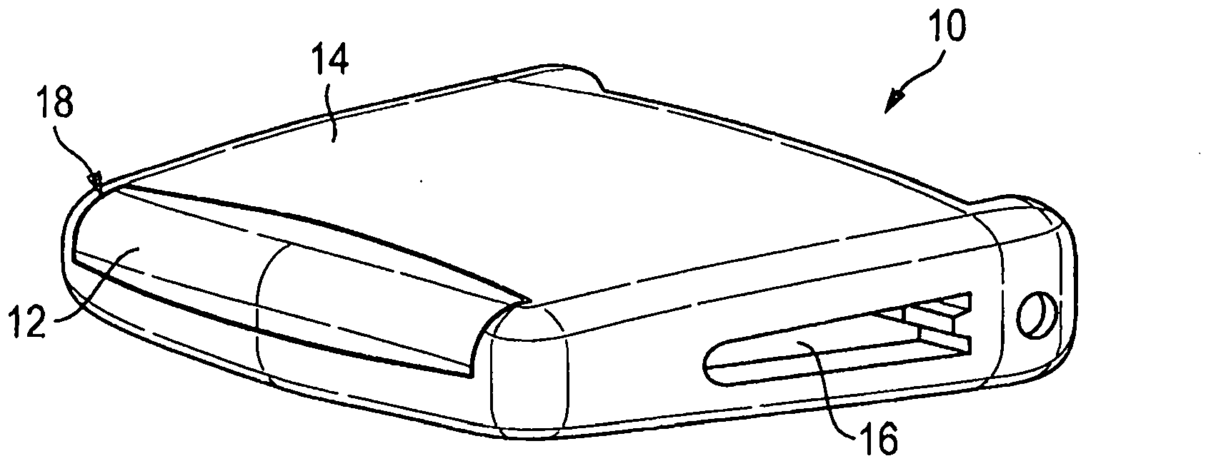
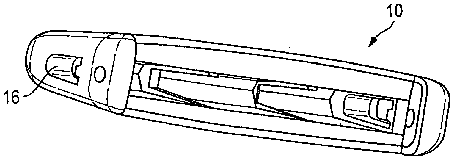
[0040] exist figure 1 and 2 A first embodiment of an operating element 10 for a fan is shown in . The operating element 10 is essentially formed from two interconnected subelements 12 , 14 . A flat channel 16 extends transversely through the entire operating element 10 from one side to the opposite side.

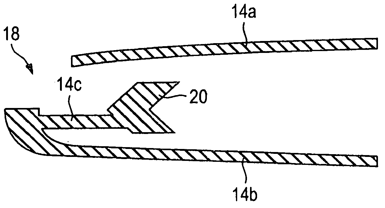
[0041] The first sub-element 12 is almost completely surrounded by the second sub-element 14 , in particular in the region where the user grips during handling. However, the front end of the first partial element 12 is visible through the recess 18 of the second partial element 14 on the front...


PUM


Abstract

In the production of a control element (10) for an air-diffuser, a first sub-element (12) made of a hard component is produced in a first injection-moulding operation, and a second sub-element (14) made of a soft component is produced in a second injection-moulding operation. The second sub-element (14) forms a bearing (20) for mounting the control element (10) on a louvre (22) of the air-diffuser. During the production of the second sub-element (14), the latter is connected to the first sub-element (12) by adhesion and / or by means of geometric shaping. The two sub-elements (12, 14) which are connected captively to each other form a premanufactured unit.

Description

technical field [0001] The invention relates to a method for producing an operating element for a fan. The invention also relates to an operating element for a ventilation device. Furthermore, the invention relates to an exhaust device, in particular an exhaust device for motor vehicles. Background technique [0002] A ventilation device with operating elements arranged on horizontal blades for controlling the air flow is known, for example, from DE 10 2006 012 473 A1. The operating element serves on the one hand to pivot the blade about its longitudinal axis and on the other hand to influence the air flow with respect to the horizontal direction of the air flow. [0003] If provision is made for the displaceability of such an operating element on the blade, it is possible to provide a bearing pad made of a soft material. However, the support pad requires additional assembly steps as a separate component. Furthermore, an insert made of metal can be embedded in the handle...

Claims


Application Information

Patent Timeline
Patent Type & Authority Applications(China)
IPC IPC(8): B60H1/34F24F13/14
CPCB60H1/3414B60H2001/3492F24F13/1426B60H1/3421B60H1/345B60H2001/3471B29C2045/1673B29C45/1657B29C45/1635B29C45/14065B29C45/1676
Inventor H·诺伊希尔S·科伯
Owner ILLINOIS TOOL WORKS INC
Why Eureka
Try Eureka