
Pseudo passive power assisting device for ankle joint movement

A power-assisted device and ankle joint technology, which is applied in the direction of appliances that help people walk, physical therapy, etc., can solve problems such as waste of energy, short continuous working time, and easy interference, and achieve easy manufacturing, energy saving, and improved utilization. Effect

Active Publication Date: 2013-04-17
WUHU HIT ROBOT TECH RES INST
View PDF15 Cites 35 Cited by
  • Summary
  • Abstract
  • Description
  • Claims
  • Application Information

AI Technical Summary

Problems solved by technology

[0003] The purpose of the present invention is to solve the problems of easy interference, short continuous working time and waste of energy in the existing assisting devices, and to provide a quasi-passive ankle joint motion assisting device

Method used


Image

  • Pseudo passive power assisting device for ankle joint movement
  • Pseudo passive power assisting device for ankle joint movement

Examples


specific Embodiment approach 1

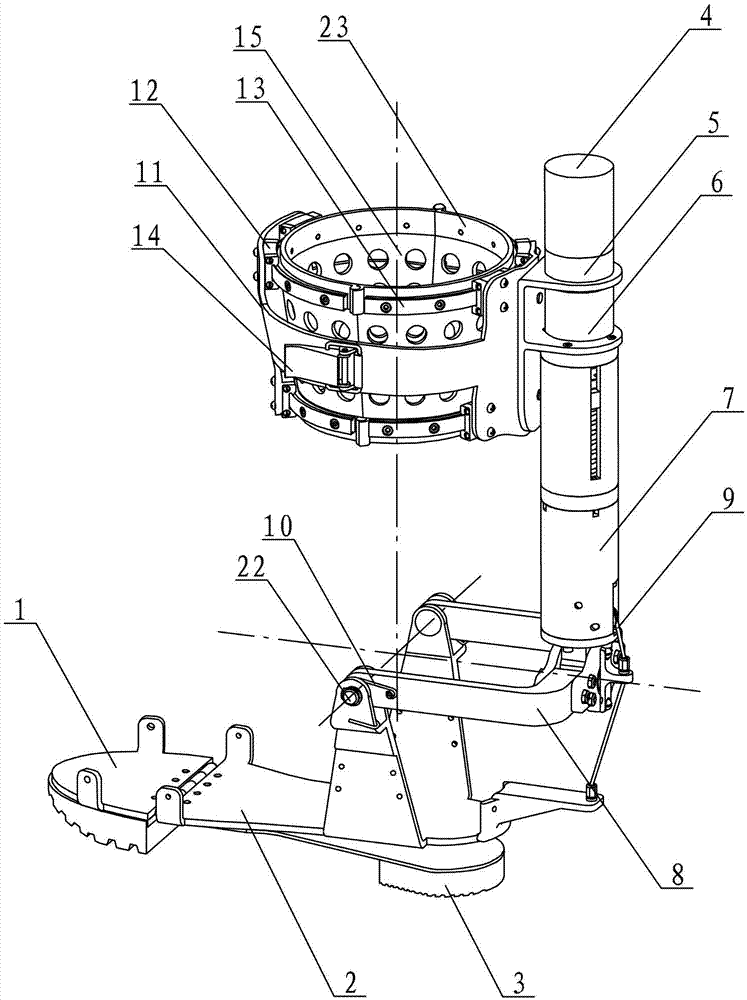
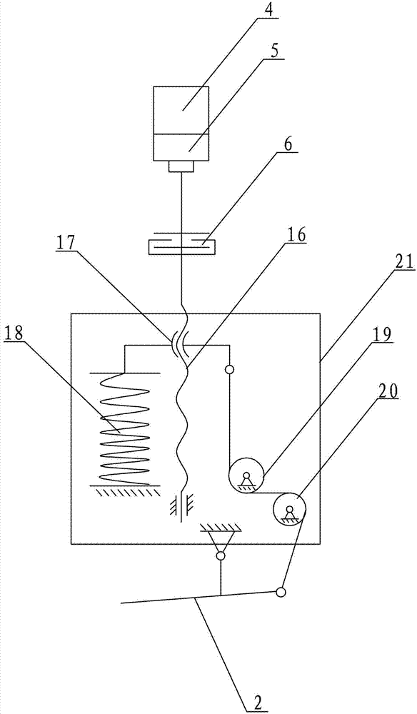
[0010] Embodiment 1: Combining figure 1 and figure 2 Describing this embodiment, a quasi-passive ankle joint motion assist device of this embodiment includes a forefoot 1, a rear sole 2 and a sole 3, the adjacent ends of the fore sole 1 and the rear sole 2 are rotatably connected, and the sole 3 is fixedly mounted on the back At the rear of the bottom end face of the sole of the foot 2, the ankle joint motion assist device also includes a drive motor 4, a reducer 5, a clutch 6, an energy storage mechanism 7, abduction or adduction joint 8, exercise wire rope 9, torsion spring 10, outer ring Frame 11, inner ring frame 15, two sets of guide rails 13, multiple chute 12, toe flexion or dorsiflexion joint 22, and internal or external rotation fixation sleeve 23, one end of the abduction or adduction joint 8 passes through toe flexion or dorsal flexion The flexion joint 22 is rotatably connected to the upper end of the rear sole 2, and a torsion spring 10 is arranged between the a...

specific Embodiment approach 2

[0011] Specific implementation mode 2: Combining figure 1 Describing this embodiment, the outer ring frame 11 of this embodiment includes a first outer ring frame and a second outer ring frame, and the first outer ring frame and the second outer ring frame are fastened to each other. It is so set up that it is easy to wear. Other components and connection relationships are the same as in the first embodiment.

specific Embodiment approach 3

[0012] Specific implementation three: combination figure 1 Describing this embodiment, the ankle joint motion assisting device of this embodiment further includes a lock 14 through which the first outer ring frame and the second outer ring frame of the outer ring frame 11 are fastened to each other. In this way, the locking is firmer and the use safety is high. Other compositions and connection relationships are the same as in the second embodiment.


PUM


Abstract

The invention discloses a pseudo passive power assisting device for ankle joint movement, and relates to the power assisting device for ankle joint movement. The invention aims to solve the problem that the existing power assisting device is easy to interfere and short in continuous work time and wastes energy sources. According to the power assisting device provided by the invention, the front sole and the rear sole is rotatably connected, the sole is fixedly installed on the rear part of the bottom end face of the rear sole, and one end of the abduction or adducted joint is rotatably connected to the upper end of the rear sole and an energy storage mechanism is arranged at the upper end at the other end of the abduction or adducted joint. The lower end of the energy storage mechanism and the other end of the abduction or adducted joint are connected trough a movement steel wire rope. The upper end of the energy storage mechanism is sequentially provided with a clutch, a reducer and a driving motor. An outer circular frame is fixedly installed on an outer ring, and an inner circular frame is arranged in the outer circular frame. Guide rails are respectively arranged on the upper and lower parts of the inner circular frame. A medial rotation or lateral rotation fixing sleeve is arranged at the upper end of the inner circular frame, and a plurality of chutes matched with the guide rails are respectively arranged on the inner wall of the outer circular frame. The pseudo passive power assisting device for ankle joint movement provided by the invention is suitable for power assist of the ankle joint.

Description

technical field [0001] The invention relates to an ankle joint motion assisting device, in particular to a quasi-passive ankle joint motion assisting device. Background technique [0002] Walking assist device is a new research field that has emerged in recent years. The assist device can enhance the strength of the lower limbs of the human body and can provide services for the elderly, disabled, soldiers and firefighters to enhance walking ability. Due to the limitation of human body structure , the existing three-degree-of-freedom wearable ankle joint assist device has the following shortcomings: 1. Usually, the internal or external rotation axis is set behind the calf, which is parallel to the internal or external rotation axis of the ankle joint of the human body, but does not coincide. Interference problems will occur, causing inconvenience to users. 2. The existing power assist device needs to carry a large amount of energy during use, which not only brings a burden t...

Claims


Application Information

Patent Timeline
Patent Type & Authority Applications(China)
IPC IPC(8): A61H3/00
Inventor 赵杰朱延河樊继壮金弘哲
Owner WUHU HIT ROBOT TECH RES INST
Learn More