
Mounting structure of machine tool centre and centre shaft

An installation structure and tip shaft technology, which is applied in the direction of tailstock/tip, toolholder accessories, turning equipment, etc., can solve the problem of difficulty in ensuring the matching accuracy of tip 1 and tip shaft 2, easy relative displacement, troublesome adjustment of tip 1, etc. Problems, achieve the effect of overcoming the defects of the installation structure, convenient correction, and good applicability

Active Publication Date: 2013-04-17
CHONGQING MACHINE TOOL GROUP
View PDF6 Cites 3 Cited by
  • Summary
  • Abstract
  • Description
  • Claims
  • Application Information

AI Technical Summary

Problems solved by technology

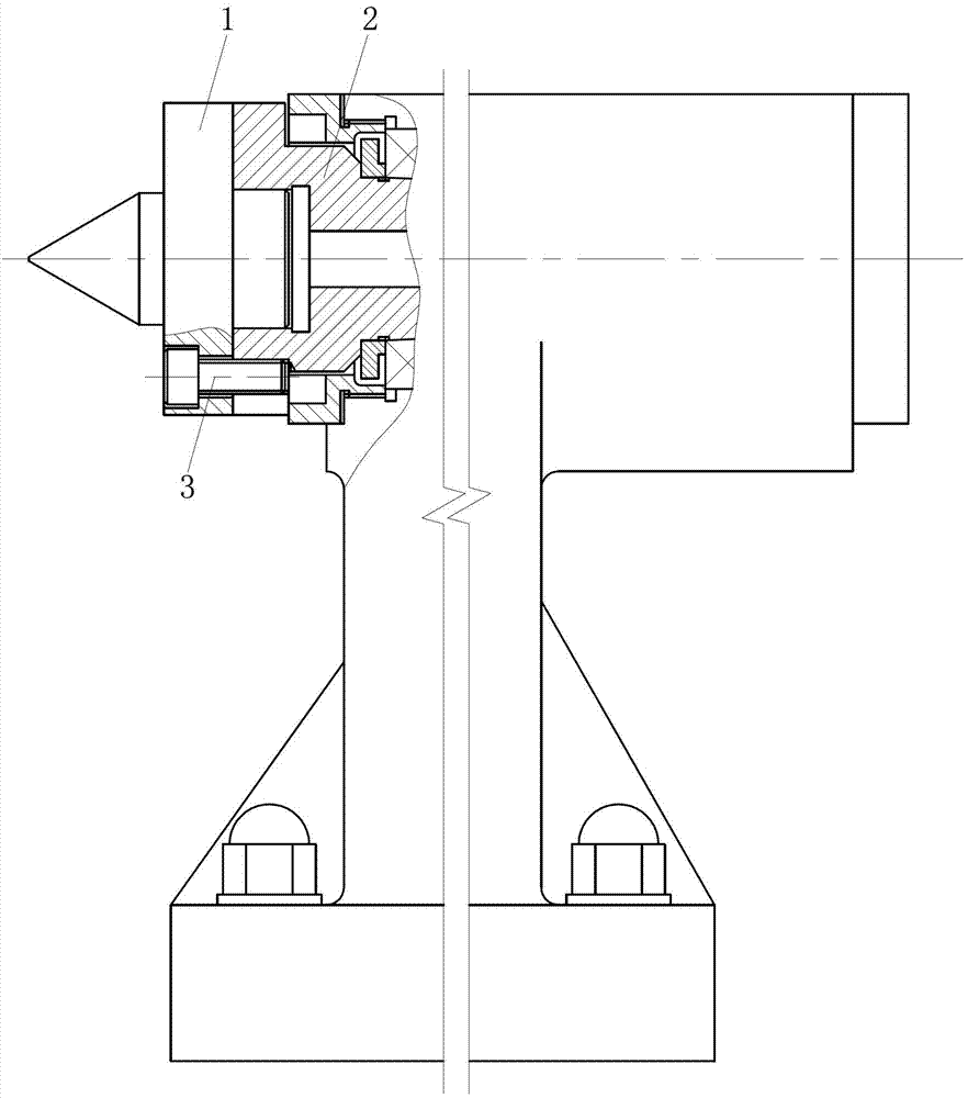
[0003] However, the traditional installation structure also has great defects, that is, the coaxial runout between the top and the top shaft must be corrected before processing, and the coaxiality requirement is high. The national standard requirement is ≤0.05mm, which leads to the Calibration is very troublesome
In addition, due to the clearance fit between the tip 1 and the tip shaft 2, the relative displacement between the tip 1 and the tip shaft 2 is easy to occur when the impact load is applied during the processing, so it is difficult to ensure the matching accuracy between the tip 1 and the tip shaft 2 , thus affecting the machining accuracy

Method used


Image

  • Mounting structure of machine tool centre and centre shaft
  • Mounting structure of machine tool centre and centre shaft
  • Mounting structure of machine tool centre and centre shaft

Examples


Embodiment Construction

[0018] Below in conjunction with accompanying drawing and embodiment the present invention will be further described:

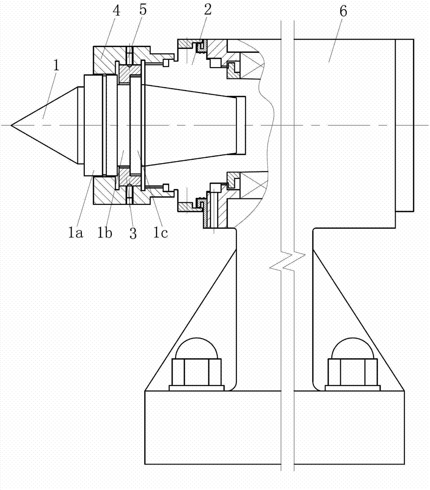
[0019] Such as Figures 2 to 6 As shown, the installation structure is composed of the top 1, the top shaft 2, the retaining ring 3, the nut sleeve 4, the locking screw 5 and the top seat 6. Wherein, the tip shaft 2 is installed in the installation hole of the tip seat 6, and its installation structure adopts the existing structure, which will not be repeated here.

[0020] The right part of the tip 1 is inserted into the mounting hole on the left part of the tip shaft 2 . As one of the improvements of the present invention, the right part of the tip 1 is a Morse taper section, and the installation hole on the left part of the tip shaft 2 is a corresponding Morse taper hole.

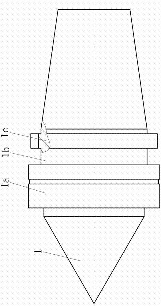
[0021] As the second improvement point of the present invention, the middle part of the shaft body of the tip 1 is sequentially composed of a large diameter section 1a, a small diamet...


PUM


Abstract

The invention discloses a mounting structure of a machine tool centre and a centre shaft. A mounting portion on the right of the centre is sleeved into a mounting hole on the left of the centre shaft, the right of the centre is a Morse taper section, and the mounting hole on the left of the centre shaft is a Morse taper hole. A large-diameter section, a small-diameter section and a key tooth section are arranged in the middle of an axial body of the centre from left to right, key teeth are arranged on the external circular surface of the key tooth section, a check ring is sleeved in the middle of the centre, the right of an inner hole of the check ring is in clearance fit with the key tooth section of the centre, the left of the inner hole of the check ring I in clearance fit with the small-diameter section of the centre, key grooves are reserved at positions, corresponding to the key teeth on the key tooth section, on the left of the inner hole of the check ring, a stopper is formed between each two adjacent key grooves and clamped between the right end face of the small-diameter section and the corresponding key tooth on the key tooth section, a nut sleeve is sleeved outside the check ring, and the right of an inner hole of the nut sleeve is in threaded connection with the left of the external circular surface of the centre. The mounting structure is not only convenient for calibration of the centre but also capable of guaranteeing matching precision of the centre and the centre shaft, and is further convenient for mounting and demounting of the centre.

Description

technical field [0001] The invention belongs to the field of machine tool tops, and in particular relates to the installation structure of machine tool tops and top shafts. Background technique [0002] Such as figure 1 As shown, the traditional installation structure of the top of the machine tool and the top shaft includes the top 1 and the top shaft 2, wherein the right part of the top 1 is inserted into the installation hole on the left part of the top shaft 2, and the cooperation between the two is a cylindrical gap Cooperate, and the tip 1 is fixedly connected with the tip shaft 2 through four connecting screws 7 . It should be pointed out that the purpose of adopting the above-mentioned installation structure is to facilitate the replacement of the tip after it is damaged. [0003] However, the traditional installation structure also has great defects, that is, the coaxial runout between the top and the top shaft must be corrected before processing, and the coaxiali...

Claims


Application Information

Patent Timeline
IPC IPC(8): B23B23/00
Inventor 张大鹏廖承渝乔丽萍唐良慧
Owner CHONGQING MACHINE TOOL GROUP
Learn More