Electrical rotary table limiting mechanism with rotary angle range not exceeding 360 degrees

A technology of turning angle range and limit mechanism, which is applied to metal processing machinery parts, large fixed members, metal processing equipment, etc., to achieve the effect of low cost and simple electrical limit mechanism

Inactive Publication Date: 2013-04-17
CHINA SHIPBUILDING IND HAIBOWEI JIANGSU TECH DEV
View PDF6 Cites 15 Cited by
  • Summary
  • Abstract
  • Description
  • Claims
  • Application Information

AI Technical Summary

Problems solved by technology

[0004] The purpose of the present invention is to overcome the defects of the prior art, in order to solve the problem of interference during installation and movement when the electrical limit angle is large, and to propose a turntable electrical limit mechanism whose rotation angle range does not exceed 360°

Method used


Image

  • Electrical rotary table limiting mechanism with rotary angle range not exceeding 360 degrees
  • Electrical rotary table limiting mechanism with rotary angle range not exceeding 360 degrees
  • Electrical rotary table limiting mechanism with rotary angle range not exceeding 360 degrees

Examples


Embodiment Construction

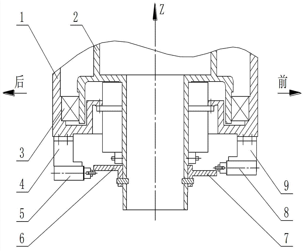
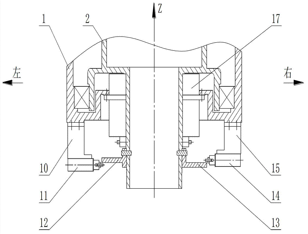
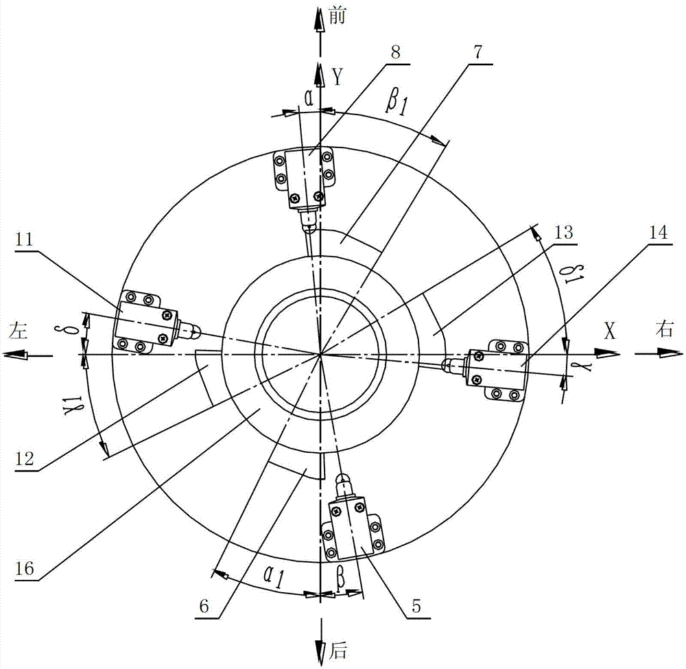
[0026] Preferred embodiments of the present invention will be described in detail below in conjunction with the accompanying drawings.

[0027] The technical solution includes: base 1, rotating shaft 2, deep groove ball bearing 3, first bracket 9, second bracket 4, third bracket 15, fourth bracket 10, first travel switch 8, second travel switch 5 , the third travel switch 14, the fourth travel switch 11, the first protrusion 6, the second protrusion 7, the third protrusion 12, the fourth protrusion 13, the annular travel stopper 16, and the resolver 17. The four brackets are connected by screws in the front, rear, left, and right directions of the base. The four brackets have different heights, different installation angles, and the same installation radius. The travel switch is installed on the bracket through screws, and the position of the travel switch can be adjusted along the radial direction of the rotating shaft.

[0028] The base 1 is a ring-shaped structure with a t...


PUM


Abstract

The invention relates to an electrical rotary table limiting mechanism with the rotary angle range not exceeding 360 degrees. The electrical rotary table limiting mechanism comprises a base, a rotary shaft, a deep groove ball bearing, a first support, a second support, a third support, a fourth support, a first travel switch, a second travel switch, a third travel switch, a fourth travel switch, a first projection, a second projection, a third projection, a fourth projection, an annular travel stopper and a rotary transformer. The electrical rotary table limiting mechanism is characterized in that the four supports are fixedly connected in the front, in the rear, on the left and on the right of the base respectively, are different in height and mounting angle and are the same in mounting radius, the annular travel stopper is sleeved on the rotary shaft below the rotary transformer, the side faces of the annular travel stopper extend outwards to form the four projections, the travel switches are fixedly connected on the supports, and when the electrical rotary table limiting mechanism is in operation, the travel switches and the four projections are used for adjusting the limiting state of a rotary table by means of butting and pressing. Therefore, the electrical rotary table limiting mechanism is simple, practical and low in cost and is capable of meeting requirements of large limiting angles.

Description

technical field [0001] The invention belongs to the technical field of turntable design, and relates to an electric limit mechanism of a turntable whose rotation angle range does not exceed 360°. Background technique [0002] For the turntable whose rotation angle range does not exceed 360°, setting two sets of electrical limit mechanisms can play the role of limit protection. Each group of electrical limit mechanisms has two sets of limit devices. The first set is the pre-limit position, which reduces the speed; the second set is the final limit position, which controls the motor to brake and stop the rotation. Each set of limit devices consists of limit switches and travel stops. [0003] When the electrical limit angle is large or the installation space is limited, there will be mutual interference during the installation and movement of each set of limit devices. Therefore, the traditional limit design method is difficult to achieve reliable limit protection. Conten...

Claims


Application Information

Patent Timeline
IPC IPC(8): B23Q1/26
Inventor 严金根沙旭南刘一鸣
Owner CHINA SHIPBUILDING IND HAIBOWEI JIANGSU TECH DEV
Why Eureka
Try Eureka