Vibrating feeder with small-space long-distance conveying chute
A long-distance conveying and vibrating feeder technology, which is applied in the direction of conveyor, vibrating conveyor, transportation and packaging, etc., can solve the problems of prolonging the conveying distance and achieve the effect of sufficient cooling time
- Summary
- Abstract
- Description
- Claims
- Application Information
AI Technical Summary
Problems solved by technology
Method used
Image

Examples
Embodiment Construction
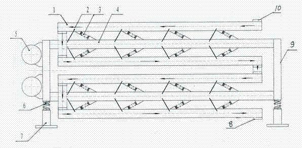
[0008] Describe embodiment in detail in conjunction with accompanying drawing, the present invention is on a pair of support 7 with vibration-damping spring 6 to be installed with a conveying frame 9, is installed with two synchronous vibrating motors 5 opposite in direction of rotation in parallel up and down at one end of the conveying frame, Two layers of crossbeams 4 are arranged on the conveying frame, and a bow-shaped conveying trough 1 with each transverse groove parallel to the crossbeam is respectively installed on the upper and lower sides of each crossbeam. The leaf springs 2 supported in a figure-eight shape are respectively provided with a main vibrating spring 3 connected to the side beam at the front end of each leaf spring, and a feed port 10 is provided at the upper end of the bow-shaped conveying horizontal trough, and a discharge port 8 is provided at the lower end . In the present invention, two anti-phase vibration motors are installed on one end of the co...
PUM
 Abstract
Description
Claims
Application Information
 - R&D
- Intellectual Property
- Life Sciences
- Materials
- Tech Scout
- Unparalleled Data Quality
- Higher Quality Content
- 60% Fewer Hallucinations
Browse by: Latest US Patents, China's latest patents, Technical Efficacy Thesaurus, Application Domain, Technology Topic, Popular Technical Reports.
© 2025 PatSnap. All rights reserved.Legal|Privacy policy|Modern Slavery Act Transparency Statement|Sitemap|About US| Contact US: help@patsnap.com