Hydraulic support

A technology of hydraulic support and cover beam, which is applied to mine roof support, mining equipment, earth-moving drilling, etc., can solve the problems of inconvenient operation, small operation space of locking mechanism, difficulty and danger of locking operation, etc.

Active Publication Date: 2014-09-10
益阳市科技成果转化服务中心 +1
View PDF7 Cites 0 Cited by
  • Summary
  • Abstract
  • Description
  • Claims
  • Application Information

AI Technical Summary

Problems solved by technology

Due to the high position and the small operating space of the locking mechanism, the locking operation is difficult and dangerous, which brings inconvenience to the actual operation

Method used


Image

  • Hydraulic support
  • Hydraulic support
  • Hydraulic support

Examples


Embodiment Construction

[0033] It should be noted that the embodiments of the present invention and the features in the embodiments can be combined with each other if there is no conflict. Hereinafter, the present invention will be described in detail with reference to the drawings and in conjunction with the embodiments.

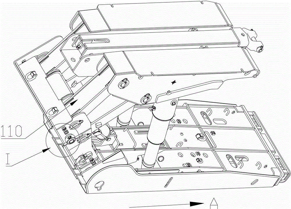
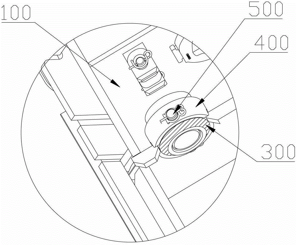
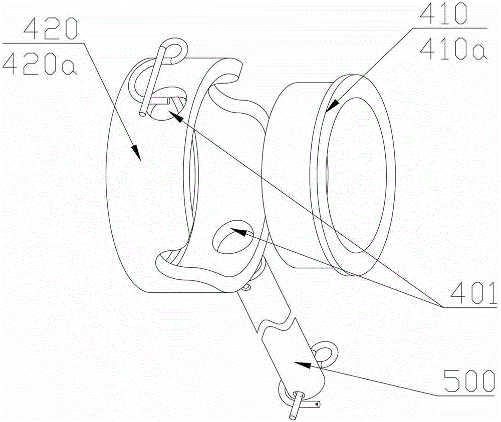
[0034] In this document, the position of the operator is determined based on the position of the operator during the coal mining operation of the hydraulic support. "Front" refers to the direction the operator faces (as indicated by arrow A in the figure), and "side" is left or right. The "outer" and "inner" are relative to the shield beam, the direction away from the shield beam is outside, and the direction close to the shield beam is inside, Figure 4 The middle arrow N points inside, and the arrow W points outside.

[0035] Please refer to figure 1 , figure 2 , image 3 with Figure 4 , figure 1 Is a schematic diagram of a three-dimensional structure of a hydraulic support provide...


PUM


Abstract

The invention discloses a hydraulic support which comprises a shield beam, a shield side guard plate, a guide rod, a locking body and a locking pin, wherein the shield side guard plate is used with the shield beam, and the outer end of the guide rod extends out of the shield beam and is connected with the shield side guard plate. The locking body is mounted on the outer side of the shield beam and forms a positioning hole, the guide rod forms a locking hole, and the locking pin is matched with the positioning hole and the locking hole in a pluggable manner when the shield side guard plate retracts. As a locking mechanism is positioned on the outer side of the shield beam, a link mechanism and other mechanisms in the front of the shield beam can be avoided, and the locking mechanism can be conveniently locked. As the outer side of the shield beam has a large space, the locking mechanism can be arranged at a lower position, and locking can be more conveniently operated by operators.

Description

Technical field [0001] The invention relates to mineral mining equipment, in particular to a hydraulic support. Background technique [0002] At present, my country's coal mining has basically achieved comprehensive mechanization. During coal mining operations, multiple hydraulic supports are usually used to support the coal mining face; the multiple hydraulic supports are arranged in order along the coal mining face in the left and right directions. [0003] A hydraulic support usually includes a base, a top beam, a shield beam and a column; the lower end of the column is connected to the base, the upper end is connected to the top beam, the upper end of the shield beam is connected to the rear end of the top beam, and the lower end is connected to the rear end of the base; the base, top beam, shield beam and The column constitutes the basic frame of the hydraulic support. In order to ensure the cooperation and sealing between the hydraulic supports, adjust the gap between the h...

Claims


Application Information

Patent Timeline
Patent Type & Authority Patents(China)
IPC IPC(8): E21D23/04
Inventor 王洪雷陈金星江亚东
Owner 益阳市科技成果转化服务中心
Why Eureka
Try Eureka