
A kind of multi-blade T-shaped tool and its processing method

A processing method and cutting tool technology, which is applied to metal processing equipment, milling cutters, manufacturing tools, etc., can solve the problems of melting chips, chip breaking, and poor chip removal, so as to reduce the phenomenon of tool breaking, prevent chip sticking, reduce Effect of small chip volume

Active Publication Date: 2022-01-25
深圳市鑫金泉精密技术有限公司
View PDF0 Cites 0 Cited by
  • Summary
  • Abstract
  • Description
  • Claims
  • Application Information

AI Technical Summary

Problems solved by technology

[0004] The purpose of the present invention is to provide a multi-edged T-shaped tool and its processing method, which is used to solve the problems of the existing T-shaped tool when it is easy to cut plastic materials, and the chips are squeezed, which leads to melting and chipping, which leads to the breaking of the tool and the problem of poor chip removal. The problem

Method used


Image

  • A kind of multi-blade T-shaped tool and its processing method
  • A kind of multi-blade T-shaped tool and its processing method
  • A kind of multi-blade T-shaped tool and its processing method

Examples


Embodiment Construction

[0034] The present invention will be further described below in conjunction with the accompanying drawings and embodiments.

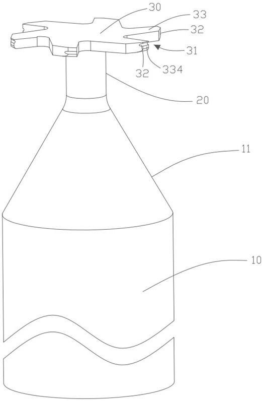
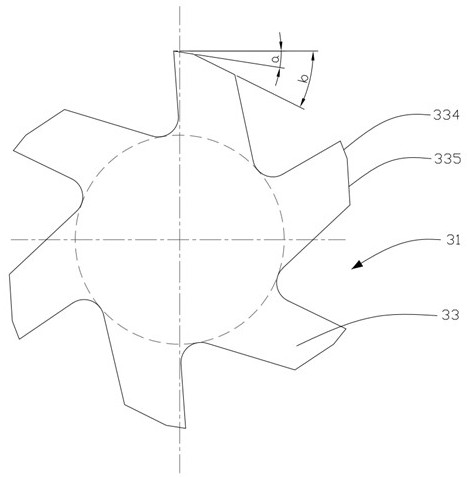
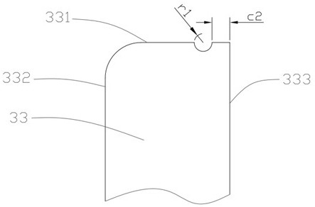
[0035] On the one hand, please refer to the attached Figure 1-5 , The invention provides a multi-edged T-shaped cutter.

[0036] The multi-edged T-shaped cutter includes: a cutter bar 10 , a neck 20 connected with the cutter bar 10 , and a cutting head 30 connected with the neck 20 . The material of the cutter bar 10 , the neck 20 and the cutting head 30 are all cemented carbide, and the neck 20 and the cutting head 30 are T-shaped. The cutting head 30 is formed with: an even number of cutting edges 33 evenly distributed, and a chip removal groove 31 between the two cutting edges 33 for chip removal. An even number of cutting edges 33 form a spiral shape. The cutting edge 33 includes a peripheral edge 331. The peripheral edge 331 includes a first relief surface 334 and a second relief surface 335. A chip breaker 32 is opened on the first relief surfa...


PUM

PropertyMeasurementUnit
surface roughnessaaaaaaaaaa
lengthaaaaaaaaaa
diameteraaaaaaaaaa

Abstract

The invention provides a multi-edged T-shaped cutter and a processing method thereof, wherein the multi-edged T-shaped cutter comprises: a cutter rod, a neck connected with the cutter rod, and a cutting head connected with the neck. The material of the cutter bar, the neck and the cutting head is hard alloy, and the neck and the cutting head are T-shaped. The cutting head is formed with: an even number of evenly distributed cutting edges, and a chip removal groove between the two cutting edges for chip removal; the even number of said cutting edges is in a spiral shape. The cutting edge includes a peripheral edge, and the peripheral edge includes a first flank and a second flank. A chip breaker is provided on the first flank, and the chip breaker is arranged radially along the first flank. The shear angle is 0°. In this way, when the tool is being processed, chips can be discharged in time, and through the chip breaker, the strength of the cutting edge can be improved, and the chip volume can be reduced, thereby reducing the generation of cutting heat and cutting stress, and preventing the product from melting. The problem of chip sticking occurs, which can reduce the phenomenon of knife breakage.

Description

technical field [0001] The invention relates to the technical field of cutters, in particular to a multi-edged T-shaped cutter and a processing method thereof. Background technique [0002] As we all know, plastic materials have poor thermal stability, high coefficient of thermal expansion, and are easy to melt at high temperatures. However, the existing T-shaped cutters for processing plastic materials have a spiral structure for chip removal, and when cutting plastic materials, chips are easily squeezed, resulting in increased cutting heat, melting of plastic products, and chip sticking of the tool. In turn, it is easy for the tool to lose cutting force, resulting in the problem of tool breakage. Moreover, the chip volume of the existing T-shaped tool will be too large, and the cutting stress will be large, which will lead to poor chip removal and the like. [0003] Therefore, the prior art needs to be improved and developed. Contents of the invention [0004] The pur...

Claims


Application Information

Patent Timeline
Patent Type & Authority Patents(China)
IPC IPC(8): B23C5/10B23P15/34
CPCB23C5/1063B23P15/34
Inventor 何灿赵晓文廖正秀
Owner 深圳市鑫金泉精密技术有限公司
Learn More