
Elastic connecting device

An elastic connection and elasticity technology, applied in the direction of elastic coupling, supporting machine, mechanical equipment, etc., can solve the problem of difficult dismantling, inability to solve the problems of eccentricity between shafts, eccentric axial deviation, affecting the six-axis adjustment frame, etc. Easy to dismantle, multi-axis docking is simple and convenient, and the effect of low friction

Active Publication Date: 2013-04-17
GUANGDONG VTRON TECH CO LTD
View PDF6 Cites 3 Cited by
  • Summary
  • Abstract
  • Description
  • Claims
  • Application Information

AI Technical Summary

Problems solved by technology

However, although it is automatic docking, the inner hexagonal connection between the shafts cannot avoid the problem of jamming due to surface contact, and it is difficult to dismantle. The dismantling process will affect the adjustment of the six-axis adjustment frame; therefore, it cannot be used as a tool, and at the same time. When the shafts are connected, the problems of eccentricity, deflection, and axial deviation between the shafts cannot be solved

Method used


Image

  • Elastic connecting device
  • Elastic connecting device
  • Elastic connecting device

Examples


Embodiment 1

[0019] Such as Figure 4 As shown in -5, it includes a motor device 3 and an elastic coupling 1. The elastic coupling 1 is connected to the motor output shaft of the motor device 3, and the motor output shaft drives the elastic coupling 1 to rotate.

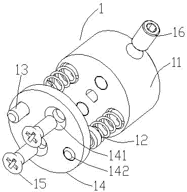
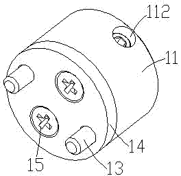
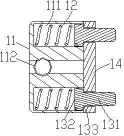
[0020] Such as Figure 9 , 10 As shown, the elastic coupling 1 includes a connecting piece 11, an elastic structure 12 arranged in the connecting piece 11, an elastic shaft 13, and a limiting plate 14, the limiting plate 14 is fixed on the connecting piece 11, and one end of the elastic shaft 13 is arranged on In the connecting piece 11 , the other end passes through the limiting plate 14 . The limit shaft sleeve 2 is provided with a clamping structure 21, which can clamp the elastic coupling 1, the elastic shaft 13 is clamped into the clamping structure 21, the elastic coupling 1 is connected with the adjustment shaft 7, and the motor The output shaft drives the adjustment shaft 7 to rotate.

[0021] Such as Image 6 As sho...

Embodiment 2

[0023] Such as figure 1 -3, on the basis of Embodiment 1, the specific elastic coupling 1 includes a connecting piece 11, an elastic structure 12 arranged in the connecting piece 11, an elastic shaft 13, a limit plate 14, and the limit plate 14 is fixed on On the connecting piece 11 , one end of the elastic shaft 13 is disposed in the connecting piece 11 , and the other end passes through the limiting plate 14 . The connecting piece 11 includes a blind hole 111 and a circumferential threaded hole 112. The elastic structure 12 is arranged in the blind hole 111. The elastic coupling 1 also includes a fixing piece 16. The fixing piece 16 connects the connecting piece 11 and the motor through the circumferential threaded hole 112. output shaft connection. The elastic coupling 1 also includes a limiting plate fixing member 15, the limiting plate 14 includes a fixing member through hole 141 and an elastic shaft through hole 142, and the limiting plate fixing member 15 passes throug...


PUM


Abstract

The invention relates to the technical field of motor connecting devices for projection display devices, in particular to an elastic connecting device. The elastic connecting device comprises a motor device, elastic couplers, a six-shaft adjusting frame, adjusting shafts and limit shaft bushings. The adjusting shafts are arranged in the six-shaft adjusting frame, and the limit shaft bushings are sleeved outside the adjusting shafts and fixedly connected with the same. Each elastic coupler is connected with a motor output shaft of the motor device and comprises a connector, an elastic structure, an elastic shaft and a limit plate, and the elastic structures, the elastic shafts and the limit plates are arranged in the connectors. The limit plates are fixed on the connectors, one ends of the elastic shafts are arranged in the connectors, and the other ends of the elastic shafts penetrate through the limit plates. Each limit shaft bushing is provided with a clamp structure, the elastic shafts are clamped into the clamp structure, the elastic couplers are connected with the adjusting shafts, and the output shaft of the motor drives the adjusting shafts to rotate. The elastic shafts and the limit shaft bushings are matched, so that connection among the shafts cannot be stuck, and wire contact is realized simultaneously. The elastic couplers are free of affection of eccentricity and angle deflection, and eccentricity and angle deflection of connection among the shafts are solved.

Description

technical field [0001] The present invention relates to the technical field of motor connection devices used in projection display devices, and more particularly, to an elastic connection device. Background technique [0002] The image signal of the existing display screen is generally adjusted through a six-axis adjustment frame. For example, Chinese patent CN102338167A discloses "a motor device for a projection display device". There is a transfer device on it, the transfer device includes a slider mechanism and a screw mechanism; the slider mechanism includes a fixed guide and a guide sleeve that can move axially relative to the fixed guide to solve the connection between the two, projection The six axes of the six-axis adjustment frame of the display device realize automatic electric adjustment. However, although it is automatic docking, the inner hexagonal connection between the shafts cannot avoid the problem of jamming due to surface contact, and it is difficult to...

Claims


Application Information

Patent Timeline
Patent Type & Authority Applications(China)
IPC IPC(8): F16D3/50F16M11/18
Inventor 杨济敏
Owner GUANGDONG VTRON TECH CO LTD
Learn More