Device and method for performing offset point automatic locking on electrooptical modulator with ultrahigh extinction ratio

An electro-optical modulator and automatic locking technology, which is applied in the field of optical communication and optical sensing, can solve the problems of feedback system discrimination influence, loss of optical coupler, limitation of output optical pulse extinction ratio, etc., achieve wide application field and increase disturbance amplitude , the effect of stabilizing the working point

Active Publication Date: 2013-04-17
NANJING UNIV
View PDF3 Cites 33 Cited by
  • Summary
  • Abstract
  • Description
  • Claims
  • Application Information

AI Technical Summary

Problems solved by technology

[0008] These three schemes are all based on the bias voltage control structure of the electro-optic modulator with optical coupler splitting in the system structure (shown in the opinion figure 2 ), this structure has certain limitations. Although the electro-optic modulator can work stably, it is difficult to realize the output of pulsed light with high extinction ratio. This structure has the following limitations:
[0009] 1) The insertion of the optical coupler brings loss, that is, the optical coupler only splits a small part of the pulsed light base into the feedback system, making the original signal-to-noise ratio of the feedback system low
[0010] 2) The extinction ratio is the ratio of the average optical power when all "0" to the average optical power when all "1", so the disturbance amplitude introduced by the pulse light substrate of this structure should not be too large, otherwise it will limit the extinction ratio of the output optical pulse, Causes the original signal-to-noise ratio to be low
[0011] 3) The optical coupler separates the optical pulse and the base signal of the optical pulse into the feedback system, which will affect the discrimination of the feedback system and also reduce the energy of the output optical pulse

Method used


Image

  • Device and method for performing offset point automatic locking on electrooptical modulator with ultrahigh extinction ratio
  • Device and method for performing offset point automatic locking on electrooptical modulator with ultrahigh extinction ratio
  • Device and method for performing offset point automatic locking on electrooptical modulator with ultrahigh extinction ratio

Examples


Embodiment Construction

[0042] Below in conjunction with accompanying drawing, technical scheme of the present invention is described in further detail:

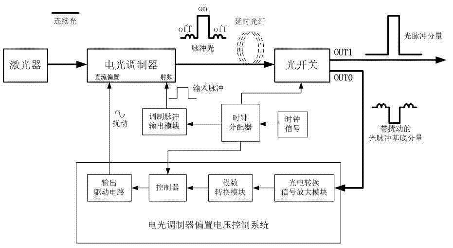
[0043] The invention is a closed-loop control device for bias voltage control of an electro-optic modulator with low duty cycle pulse light modulation. It mainly includes three modules: optical splitting module, electro-optic modulator bias voltage control module, and synchronization module.

[0044] The optical splitting module is mainly an optical switch, and the optical switch required by the device must be a high-speed optical switch with one input and two outputs. The main function of this optical switch is to separate the optical pulse component of the pulsed light modulated by the electro-optic modulator from the optical pulse base component, so that the optical pulse can be stably detected with high energy, and the optical pulse base signal is all biased by the electro-optic modulator. The control system receives the processing. Therefore...


PUM


Abstract

The invention discloses a device and a method for performing offset point automatic locking on an electrooptical modulator with ultrahigh extinction ratio. The offset point automatic locking device of the electrooptical modulator with ultrahigh extinction ratio comprises a laser, an electrooptical modulator, an optical switch, an electrooptical modulator offset voltage control system and a clock synchronization module, wherein the electrooptical modulator offset voltage control system comprises an electrooptical conversion signal amplification module, an analog-digital conversion module, a controller and an output driving circuit; and the clock synchronization module is used for opening an synchronization optical switch, inputting modulated electrical impulse of the electrooptical modulator radio-frequency end, and the disturbance leading-in time of the direct-current offset end of the electrooptical modulator. The method is characterized in that ultrahigh extinction ratio pulsed light output is realized through the cascade connection of the electrooptical modulator and the optical switch, and through controlling the offset voltage of the electrooptical modulator, the electrooptical modulator operates at an appropriate working spot stably. According to the invention, the offset voltage of the electrooptical modulator is controlled automatically; the pulsed light extinction ratio output by the device is improved greatly; and the energy is higher and much stable.

Description

technical field [0001] The invention relates to a bias voltage driver developed for electro-optic modulators with low duty cycle pulsed light modulation, and relates to the fields of optical communication and optical sensing that require ultra-high extinction ratio optical pulses. Background technique [0002] Electro-optic modulator is a device that uses the electro-optic effect of certain crystals to modulate optical signals. It is widely used in high-speed optical communication, optical fiber sensing and other fields. Electro-optic modulation can be divided into longitudinal electro-optic modulation and transverse electro-optic modulation according to the direction of the applied electric field; according to the different modulation types, it can be divided into electro-optic phase modulation and electro-optic intensity modulation. The output characteristic curve of a typical electro-optic modulator is shown in the diagram image 3 ,Depend on image 3 It can be seen that ...

Claims


Application Information

Patent Timeline
Patent Type & Authority Applications(China)
IPC IPC(8): G02F1/03
Inventor 张益昕张旭苹武学林应宙锋
Owner NANJING UNIV
Why Eureka
Try Eureka