A laser drive current expansion system

A technology for driving current and lasers, which is applied in the field of current expansion, which can solve the problems of weak output optical power, failure to meet the needs of application environments with higher and higher temperatures, output optical power jumps, etc., and achieve stable output optical power. Effect

Active Publication Date: 2022-03-01
THE 44TH INST OF CHINA ELECTRONICS TECH GROUP CORP
View PDF10 Cites 0 Cited by
  • Summary
  • Abstract
  • Description
  • Claims
  • Application Information

AI Technical Summary

Problems solved by technology

[0003] In the previous optical module design research, the basic consideration was the conventional application environment such as the temperature below 85°C. If the temperature exceeded 85°C, a fixed bias current was used to drive the bias current. There is no corresponding adjustment mechanism for the bias current as the temperature changes. The output optical power will jump; at the same time, with the increase of temperature, the output optical power will also be greatly weakened
Therefore, the optical module using a fixed bias current driving mechanism can no longer meet the requirements of the application environment with higher and higher temperatures, so it is necessary to conduct special research on the driving technology of lasers exceeding 85 °C

Method used


Image

  • A laser drive current expansion system

Examples


Embodiment Construction

[0014] The present invention will be further described below with reference to the accompanying drawings.

[0015] In the description of the present invention, it is necessary to explain that the term "connection" is needed, unless otherwise specified and defined, and, for example, a mechanical connection or electrical connection, or an inner communication inside the two elements, may be Directly, it can also be indirectly connected via an intermediate medium, and for those skilled in the art, the specific meaning of the above terms can be understood according to the specific situation.

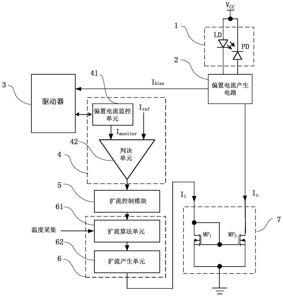
[0016] Such as figure 1 As shown, a circuit diagram of a preferred embodiment of a laser driving current spreading system according to the present invention. One laser drive current spreading system includes a laser 1, a bias current generating circuit 2, a driver 3, a comparison module 4, an expansion control module 5, a spread processing module 6, and a current mirror 7, the laser 1 Connecting ...


PUM


Abstract

The invention discloses a laser drive current expansion system, which includes a laser, a bias current generation circuit, a driver, a comparison module, a current expansion control module, a current expansion processing module and a current mirror. The laser is used to detect light and generate light current; the bias current generation circuit is used to adjust the output optical power of the laser; the driver is used to drive the laser to work; the comparison module is used to generate a modulation current to control the expansion through the current expansion control module The stream processing module is turned on or off; the current expansion processing module is used to generate an output current, and the current mirror is used to copy and amplify the output current to obtain an expanded current; to compensate the bias current to ensure that after compensation The bias current can drive the laser to work normally and stabilize the output optical power of the laser.

Description

Technical field [0001] The present invention relates to the field of current spreading techniques, and more particularly to a laser driven current expansion system. Background technique [0002] The optical module is one of the core devices of modern optical communication, and the performance of performance must be maintained within a wide range of temperature variations. For special applications such as ambient temperature exceeding 85 ° C, the optical module internal driver cannot provide the bias current required by the laser assembly, and the output optical power of the optical module will cause a dramatic jump, forcing the light emission part of the eye to be deteriorated, and light receives Some sensitivity deteriorate, eventually causing an increase in communication error rate. Therefore, it is very important to provide a sufficient drive current to the laser, which is very important for the drive current. [0003] In the conventional optical module design studies, the tem...

Claims


Application Information

Patent Timeline
Patent Type & Authority Patents(China)
IPC IPC(8): H01S5/042H02M3/156
CPCH01S5/042H02M3/156
Inventor 周本军胡伟张敏蒋利群贺燕
Owner THE 44TH INST OF CHINA ELECTRONICS TECH GROUP CORP
Why Eureka
Try Eureka