
Semiconductor laser and its temperature control method

A temperature control method and temperature control technology, which can be applied to semiconductor lasers, lasers, laser parts, etc., can solve the problems of lowering refrigeration efficiency, affecting the reliability of projection devices, and lowering optical power, and achieving the effect of preventing water vapor condensation.

Active Publication Date: 2020-12-04
APPOTRONICS CORP LTD
View PDF6 Cites 0 Cited by
  • Summary
  • Abstract
  • Description
  • Claims
  • Application Information

AI Technical Summary

Problems solved by technology

However, there are the following problems that are difficult to solve: First, the working shell temperature of the laser is lower than the ambient temperature. When the ambient humidity is high, the water vapor in the air will condense on the surface of the TEC cold end and other surfaces whose temperature is lower than the ambient temperature, which may lead to a drop in optical power. , short circuit, damaged optical parts and other product failures seriously affect the reliability of the projection device; second, as the ambient temperature rises, the temperature difference between the hot and cold ends of the TEC increases, and the cooling efficiency COP of the TEC drops rapidly, resulting in a breakdown of the projection device. Efficiency drops

Method used

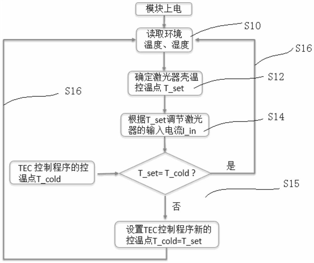
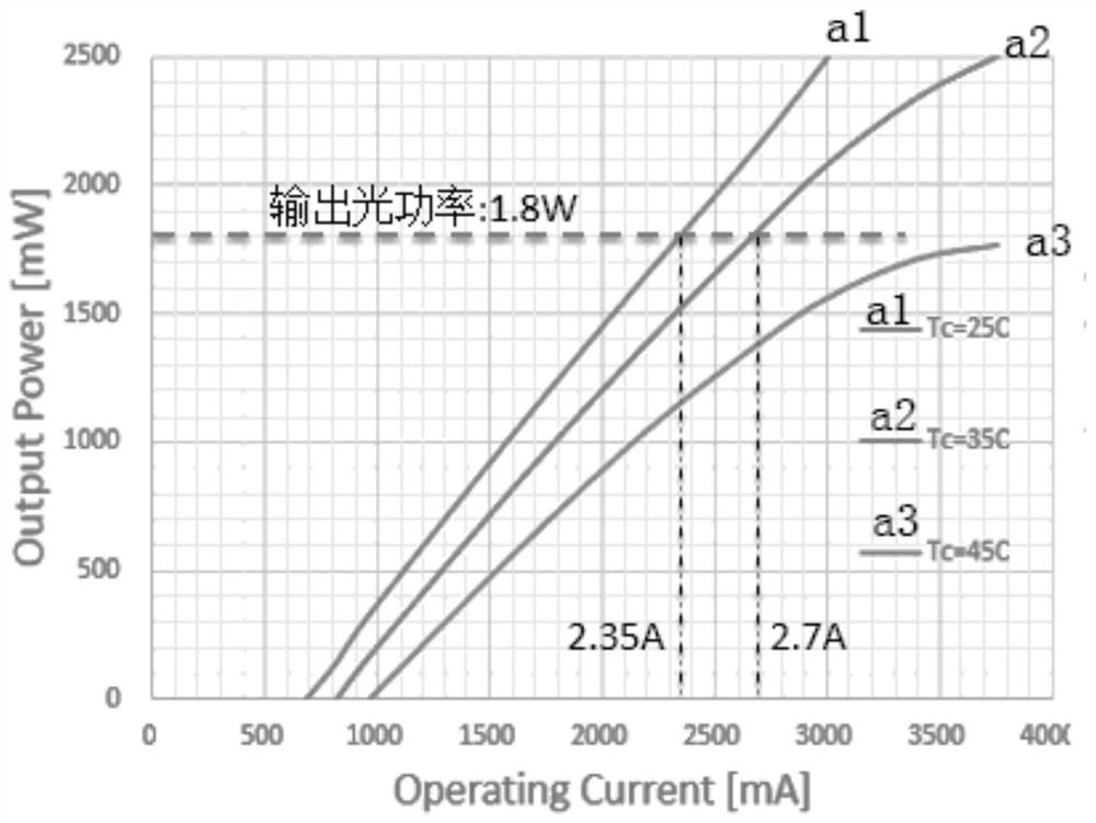

Image

  • Semiconductor laser and its temperature control method
  • Semiconductor laser and its temperature control method
  • Semiconductor laser and its temperature control method

Examples


Embodiment 1

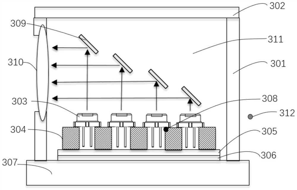
[0054] The method for controlling the temperature of a semiconductor laser provided in Embodiment 1 is based on a semiconductor laser. The semiconductor laser has an accommodating cavity, and a laser and a cooling mechanism for controlling the temperature of the laser are installed in the accommodating cavity.

[0055] Specifically, please refer to figure 1 , figure 1 What is shown is a specific example of the above-mentioned semiconductor laser, and is not the only choice of the temperature control method shown in this embodiment.

[0056] Wherein, the red laser 303 is installed on the bottom plate 304 , and the bottom plate 304 is connected with the heat sink 307 through the heat soaking plate 305 and the cooling mechanism (TEC) 306 . The bottom plate 304 is fixed on the heat sink 307 by means of elastic connection (the fixing method is not shown in the figure), and the contact surfaces are tightly bonded by high thermal conductivity silicone grease or other low thermal re...

Embodiment 2

[0086] Please refer to Figure 5 The method for controlling the temperature of a semiconductor laser provided in Embodiment 2 is based on a semiconductor laser. The semiconductor laser has an accommodating cavity 311, and the accommodating cavity 311 is equipped with a laser 303 and a cooling mechanism 306 for controlling the temperature of the laser.

[0087] Specifically, Figure 5Shown is a specific example of the above-mentioned semiconductor laser, and its difference from the example structure of the first embodiment is that the temperature and humidity sensor 313 is defined as the second parameter detection mechanism, which is arranged in the accommodating cavity 311 and located in the laser 303 , used to collect the temperature T_air of the space around the laser 303 in the accommodating cavity 311 . In this way, as the temperature in the accommodating cavity 311 rises, the working shell temperature of the laser 303 is increased synchronously.

[0088] The temperatur...

Embodiment 3

[0109] Embodiment 3 provides another temperature control method of a semiconductor laser, which adopts the combination of Embodiment 1 and Embodiment 2.

[0110] The temperature control method includes a first temperature control mode and a second temperature control mode, and the first temperature control mode and the second temperature control mode can be selectively switched.

[0111] Wherein, the first temperature control mode is the temperature control method shown in the first embodiment, and the second temperature control mode is the temperature control method shown in the second embodiment. The first temperature control mode is mainly used to determine the working shell temperature of the laser according to the temperature and humidity of the application environment. In general, the change of the temperature and humidity of the environment is relatively slow, and this method can be used normally. However, in some cases, such as when the equipment is subjected to a temp...


PUM


Abstract

A semiconductor laser and a temperature control method therefor, comprising: firstly collecting the temperature and humidity of an external environment of a semiconductor laser or the temperature and humidity in an accommodating cavity body (311); then according to the collected temperature and humidity, determining a working case temperature which can prevent a water vapor condensation phenomenon, so as to adjust a temperature control point according to the determined working case temperature; and according to a function relationship between an input current and the working case temperature and output light power of the laser, calculating the input current corresponding to the present working case temperature and adjusting same under the precondition of ensuring that the output light power of the laser is roughly stable. According to the temperature control method, by monitoring a change in the temperature and humidity of an environment / cavity body, a working case temperature and a power supply current of a laser is adjusted in real time, both preventing water vapor condensation and ensuring stable output light power.

Description

technical field [0001] The present application relates to semiconductor lasers, in particular to a temperature control method in semiconductor lasers. Background technique [0002] Laser light sources have the advantages of high brightness, wide color gamut, good reliability, energy saving and environmental protection, and are more and more widely used in various projection devices. Semiconductor lasers are commonly used as laser light sources, and their electro-optical conversion efficiency and reliability are closely related to the working shell temperature of the laser. For example, when the shell temperature of a red laser diode is 25°C, the input current is 3A, and the laser can output 2.5W red light; when the shell temperature is 35°C, the same output is 2.5W red light, and the input current needs to reach 3.75A, that is, the input power needs to be increased at least 25%. Therefore, for this type of semiconductor laser, in order to obtain better electro-optical effi...

Claims


Application Information

Patent Timeline
Patent Type & Authority Patents(China)
IPC IPC(8): H01S5/024
CPCH01S5/024
Inventor 胡飞谭大治李屹
Owner APPOTRONICS CORP LTD
Learn More