Laser drive circuit

A driving circuit and laser technology, applied in lasers, laser parts, semiconductor lasers, etc., can solve the problems of lack of access and mobility, and achieve the effects of high reliability, high integration and low noise

Active Publication Date: 2020-04-10
SHANGHAI AEROSPACE SCI & IND ELECTRIC APPLIANCE RES INST
View PDF12 Cites 0 Cited by
  • Summary
  • Abstract
  • Description
  • Claims
  • Application Information

AI Technical Summary

Problems solved by technology

Optical fiber can provide an ultra-wide bandwidth window with a potential bandwidth of 20THz and maintain low loss over long distances, but it lacks flexible access methods and mobility

Method used


Image

  • Laser drive circuit
  • Laser drive circuit
  • Laser drive circuit

Examples


Embodiment Construction

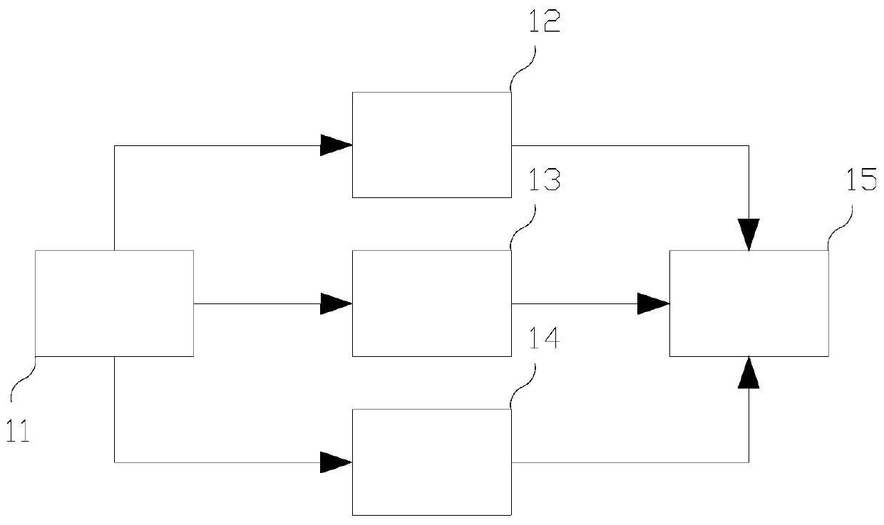
[0025] as the picture shows, figure 1 It is a circuit block diagram of the present invention, a laser drive circuit, including: a power supply circuit 11, the drive circuit is powered by a +5V single power supply circuit 11, which meets the power supply requirements of the drive circuit; wherein, the power supply circuit 11 is connected to a voltage conversion circuit 12 for The conversion from positive pressure to negative pressure also includes: a temperature control circuit 14 connected to the power circuit 11, used to control the thermoelectric cooler inside the laser according to the ambient temperature change; the power circuit 11 is also connected to an automatic power control circuit 13. The automatic power control circuit 13 is connected with the laser bias circuit 15, and is used for feedback control of the laser bias circuit 15 according to the output voltage of the monitoring detector integrated inside the laser.

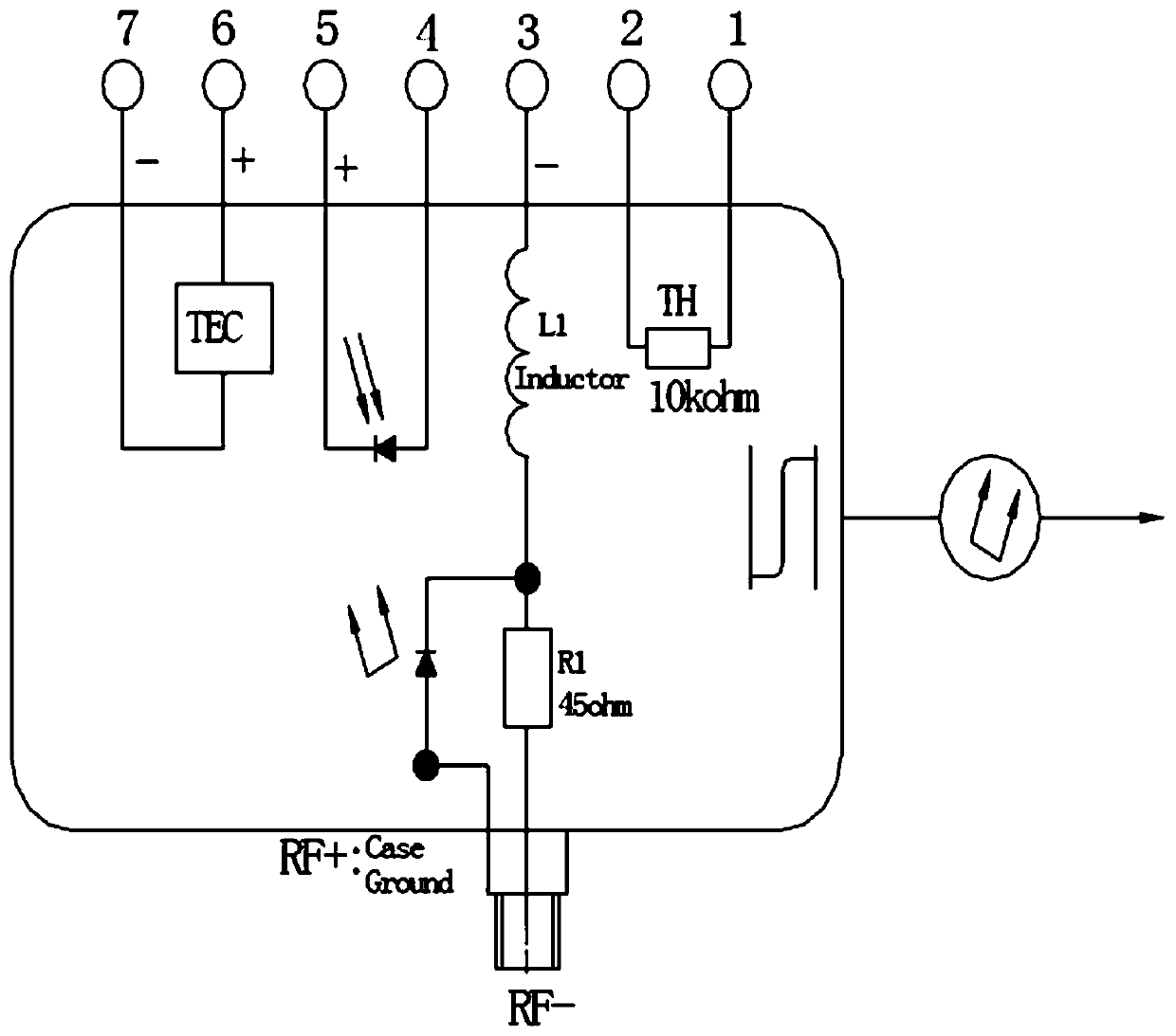
[0026] as the picture shows, figure 2 It is the ...


PUM


Abstract

The invention discloses a laser driving circuit. The circuit comprises a power source circuit; the power source circuit is connected with a voltage conversion circuit and is used for performing positive-to-negative voltage conversion; the circuit further comprises a temperature control circuit connected with the power source circuit and is used for controlling a thermoelectric refrigerating unit inside a laser according to the change of ambient temperature; the power source circuit is connected with an automatic power control circuit; and the automatic power control circuit is connected with alaser bias circuit and is used for performing feedback control on the laser bias circuit according to a voltage outputted by a monitoring detector integrated in the laser. According to the laser driving circuit of the invention, the laser bias circuit and the temperature control circuit work cooperatively, so that the bias current of the laser can be dynamically adjusted, and therefore, the output optical power of the laser can be stable, and low-noise, high-integration, high-reliability and wide-temperature range operation can be realized.

Description

technical field [0001] The present invention relates to a driving circuit, in particular to a direct modulation laser driving circuit for optical wireless communication. Background technique [0002] At present, compared with wireless communication, optical fiber communication has the characteristics of low loss, wide frequency bandwidth, and strong anti-electromagnetic interference ability, providing massive bandwidth and ultra-high speed rate. Compared with the loss of radio waves in space and transmission lines, the loss of optical fiber communication is very low. Optical fiber can provide an ultra-wide bandwidth window with a potential bandwidth of 20 THz and maintain low loss over long distances, but it lacks flexible access methods and mobility. [0003] In order to meet the needs of large bandwidth and flexible allocation of communication, the combination of microwave communication technology and optical fiber communication technology, Radio over Fiber (RoF) technolo...

Claims


Application Information

Patent Timeline
Patent Type & Authority Patents(China)
IPC IPC(8): H01S5/042
CPCH01S5/042H01S5/0425H01S2301/17
Inventor 刘国栋
Owner SHANGHAI AEROSPACE SCI & IND ELECTRIC APPLIANCE RES INST
Why Eureka
Try Eureka