Circuit and method for automatically stabilizing output optical power of optical module

An automatic stabilization and light output technology, applied in the direction of adjusting electrical variables, control/regulating systems, instruments, etc., can solve the problem of long compensation time, and achieve the effect of avoiding laser aging.

Active Publication Date: 2022-04-05
THE 44TH INST OF CHINA ELECTRONICS TECH GROUP CORP
View PDF4 Cites 0 Cited by
  • Summary
  • Abstract
  • Description
  • Claims
  • Application Information

AI Technical Summary

Problems solved by technology

[0003] In order to solve the problem of long compensation time of conventional APC automatic control technology, the present invention proposes an optical module output optical power automatic stabilization circuit and method, the circuit includes LD laser components, PD laser components, PD current detection circuit 1, comparator 2 , gating controller 3, secondary approximation algorithm processing center 4, self-increasing algorithm processing center 5 and bias current generation circuit 6, PD current detection circuit 1 detects the back detection current of the PD laser component, and comparator 2 according to the back detection The relationship between the current and the index current outputs a gating control signal, and the gating controller 3 decides to use a quadratic approximation algorithm according to the gating control signal. The algorithm processing center 5 fine-tunes the bias current value, and the bias current generation circuit 6 generates a bias current according to the obtained bias current value and the fine-tuned bias current value, and drives the LD laser component

Method used


Image

  • Circuit and method for automatically stabilizing output optical power of optical module

Examples


Embodiment Construction

[0024] The following will clearly and completely describe the technical solutions in the embodiments of the present invention with reference to the accompanying drawings in the embodiments of the present invention. Obviously, the described embodiments are only some, not all, embodiments of the present invention. Based on the embodiments of the present invention, all other embodiments obtained by persons of ordinary skill in the art without making creative efforts belong to the protection scope of the present invention.

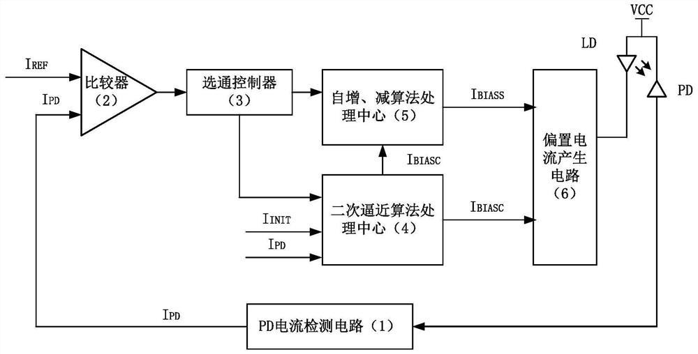
[0025] The present invention proposes an optical module output optical power automatic stabilization circuit including LD laser components, PD laser components, PD current detection circuit 1, comparator 2, gating controller 3, secondary approximation algorithm processing center 4, self-increasing algorithm The processing center 5 and the bias current generation circuit 6, the PD current detection circuit 1 detects the back detection current of the PD laser com...


PUM


Abstract

The invention belongs to the field of optoelectronic devices, and particularly relates to an optical module output optical power automatic stabilizing circuit and method, and the circuit comprises an LD laser assembly, a PD laser assembly, a PD current detection circuit, a comparator, a gating controller, a secondary approximation algorithm processing center, an automatic increase and decrease algorithm processing center, and a bias current generation circuit. The PD current detection circuit detects the back detection current of the PD laser assembly, the comparator outputs a gating control signal according to the relation between the back detection current and the index current, and the gating controller determines to use the secondary approximation algorithm processing center according to the gating control signal to quickly obtain the bias current value meeting the requirement by adopting the secondary approximation algorithm. Fine adjustment is carried out on the bias current value through the automatic increase and decrease algorithm processing center, and the bias current generating circuit generates bias current according to the obtained bias current value and the finely-adjusted bias current value; the problem of output optical power decline caused by aging of the laser in the optical module is solved.

Description

technical field [0001] The invention belongs to the field of optoelectronic devices, in particular to a circuit and method for automatically stabilizing the output optical power of an optical module. Background technique [0002] For existing digital optical modules, the technologies used to stabilize the transmitted optical power mainly include the following: (1) Temperature compensation method: This method needs to preset the temperature range lookup table, then monitor the ambient temperature in real time, and calculate the temperature range according to the ambient temperature And query the corresponding data from the lookup table, and write it into the driver to update the bias current. The disadvantage of this method is that the output optical power will jump to a certain extent when the temperature range changes, which will affect the bit error rate, and it cannot avoid optical The output optical power decline caused by the aging of the laser inside the module. (2) K...

Claims


Application Information

Patent Timeline
Patent Type & Authority Applications(China)
IPC IPC(8): G05F1/66
Inventor 周本军胡伟饶垚叶峻宏
Owner THE 44TH INST OF CHINA ELECTRONICS TECH GROUP CORP
Why Eureka
Try Eureka