Rocker switch forcibly disconnected by rotating button cover

A rocker switch and button technology, applied in the direction of electrical components, etc., can solve problems such as arcing, high temperature, silver point sintering, etc., achieve the effect of wide application range, prevent equipment failure and safety accidents

Active Publication Date: 2013-04-17
浙江上开汽车电器股份有限公司
View PDF4 Cites 1 Cited by
  • Summary
  • Abstract
  • Description
  • Claims
  • Application Information

AI Technical Summary

Problems solved by technology

[0002] For high-current inductive loads, electric tool loads and capacitive loads that use rocker switches as power switches, because inductive loads and electric tool loads will generate an inrush current about 6 times the rated current when starting, and capacitive The load has a discharge impulse current (the impulse current is related to the capacitor capacity and is proportional), resulting in arcing and high temperature; when the instantaneous current is large, the switch dynamic point and static point will be sintered together, so that the switch cannot work normally. After the external power supply is turned off, the switch can work again after the internal temperature of the switch drops, but the silver point sintering phenomenon will still occur during the follow-up work

Method used


Image

  • Rocker switch forcibly disconnected by rotating button cover
  • Rocker switch forcibly disconnected by rotating button cover
  • Rocker switch forcibly disconnected by rotating button cover

Examples


Embodiment 1

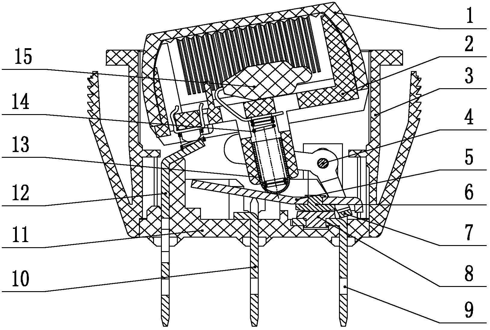
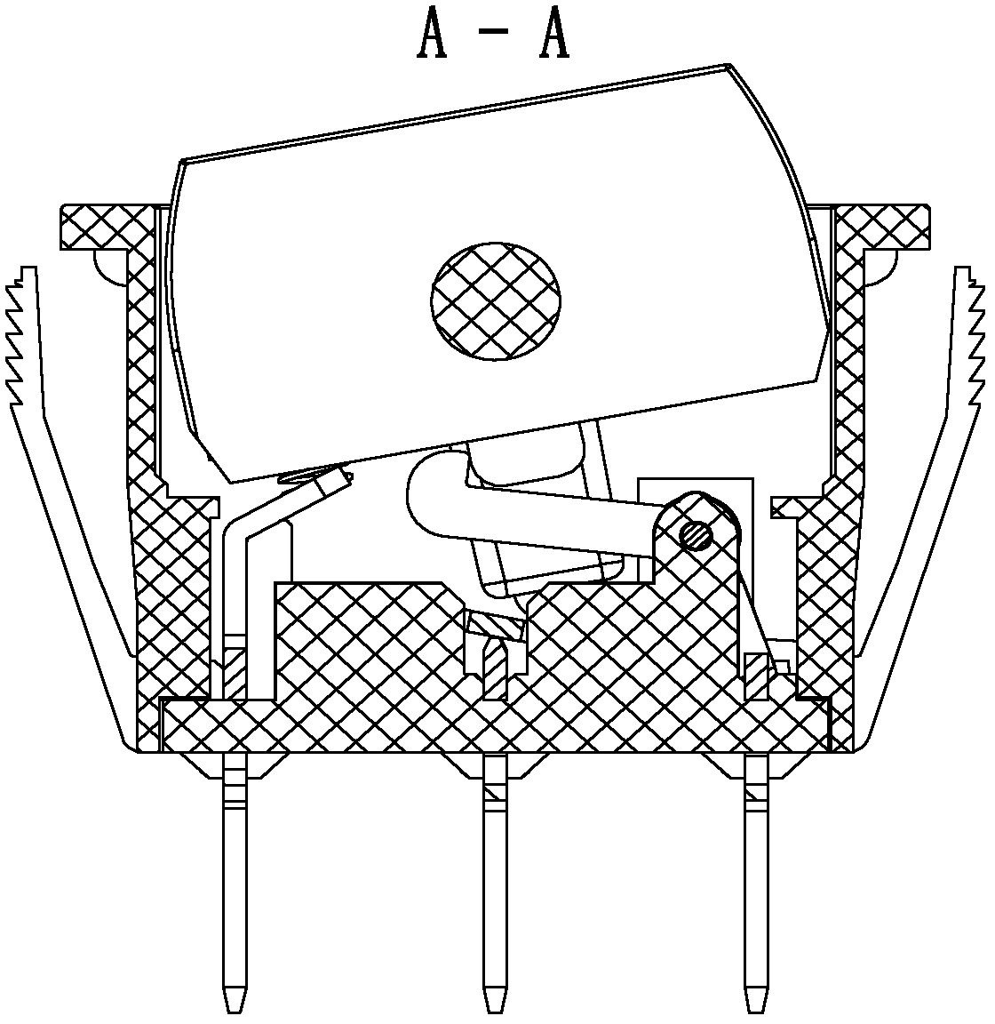
[0024] like Figure 1-3 , 5a, a rocker switch that is forced to disconnect when the button cover rotates. 7. Edge contact pin 9, static contact 8, middle contact pin 10, base 11, slide tube 13, spring 14, illuminant 15, the button cover 1 is covered on the button seat 2, the button cover 1 and the button The seat 2 is located in the shell 3, and the button seat 2 is provided with a sliding cylinder 13, the lower end of the sliding cylinder 13 touches the moving contact piece 5, and can slide on the moving contact piece 5, and the center of the forcing rod 7 is set on the On the rotating shaft 4, the forcing rod 7 can rotate on the rotating shaft 4. There is a boss below the button seat 2. One end of the forcing rod 7 is connected to the button seat 2, and is closely matched with the boss below the button seat 2. The contact pieces 5 are in clearance fit, the movable contact 6 is arranged on the movable contact piece 5, and can move up and down with the movable contact piece, ...

Embodiment 2

[0028] like Figure 4b As shown, the top of the exposed part of the button cover is a V-shaped surface, and the middle movable part of the button cover part adopts a steel ball structure, such as Figure 5b shown. All the other are with embodiment 1.

Embodiment 3

[0030] like Figure 4c As shown in , the top of the exposed part of the button cover is a curved surface. All the other are with embodiment 1.


PUM


Abstract

The invention relates to a rocker switch forcibly disconnected by rotating a button cover. The rocker switch consists of the button cover, a button seat, a shell, a rotating axis, a movable contact spring, a movable contact, a forcible bar, side contact legs, a static contact, a middle contact leg, a base, and a sliding tube or a steel ball, wherein the button cover is covered on the button seat, the button cover and the button seat are positioned in the shell, the sliding tube or the steel ball is arranged below the button seat, the center of the forcible bar is arranged on the rotating axis, one end of the forcible bar is connected with the button seat, the other end is in clearance fit with the movable contact spring, the movable contact is arranged on the movable contact spring, the static contact is arranged on the base and opposite to the movable contact spring above the static contact, and the side contact legs are arranged at two ends of the base, and the middle contact leg is arranged in the middle of the base. Compared with the prior art, the rocker switch has the advantages of being wide in use range, safe and reliable, and the like.

Description

technical field [0001] The invention relates to a power switch, in particular to a rocker switch which is forcibly disconnected by the rotation of a button cover. Background technique [0002] For high-current inductive loads, electric tool loads and capacitive loads that use rocker switches as power switches, because inductive loads and electric tool loads will generate an inrush current about 6 times the rated current when starting, and capacitive The load has a discharge impact current (the impact current is related to the capacitance, which is proportional), resulting in arcing and high temperature; when the instantaneous current is large, there will be a phenomenon that the switch dynamic point and static point are sintered together, so that the switch cannot work normally. After the external power supply is turned off, the switch can work again after the internal temperature of the switch drops, but the silver point sintering phenomenon will still appear during the fol...

Claims


Application Information

Patent Timeline
Patent Type & Authority Applications(China)
IPC IPC(8): H01H21/36
Inventor 朱晓东
Owner 浙江上开汽车电器股份有限公司
Why Eureka
Try Eureka