
Plane reflector concaved at side edge

A technology of planar reflection and reflector, which is applied in the field of radio frequency identification, and can solve the problems of application limitations of RFID tags, etc.

Inactive Publication Date: 2013-04-17
SHANGHAI HUAHONG JITONG SMART SYST
View PDF8 Cites 0 Cited by
  • Summary
  • Abstract
  • Description
  • Claims
  • Application Information

AI Technical Summary

Problems solved by technology

[0014] The purpose of the present invention is to provide a planar reflector, which is applied to a planar antenna to offset the radiation signal of the antenna in one direction, and realize a planar unidirectional antenna, so as to solve the problem of existing RFID tags in book management and item management on the assembly line. application limitations

Method used


Image

  • Plane reflector concaved at side edge
  • Plane reflector concaved at side edge
  • Plane reflector concaved at side edge

Examples


Embodiment 1

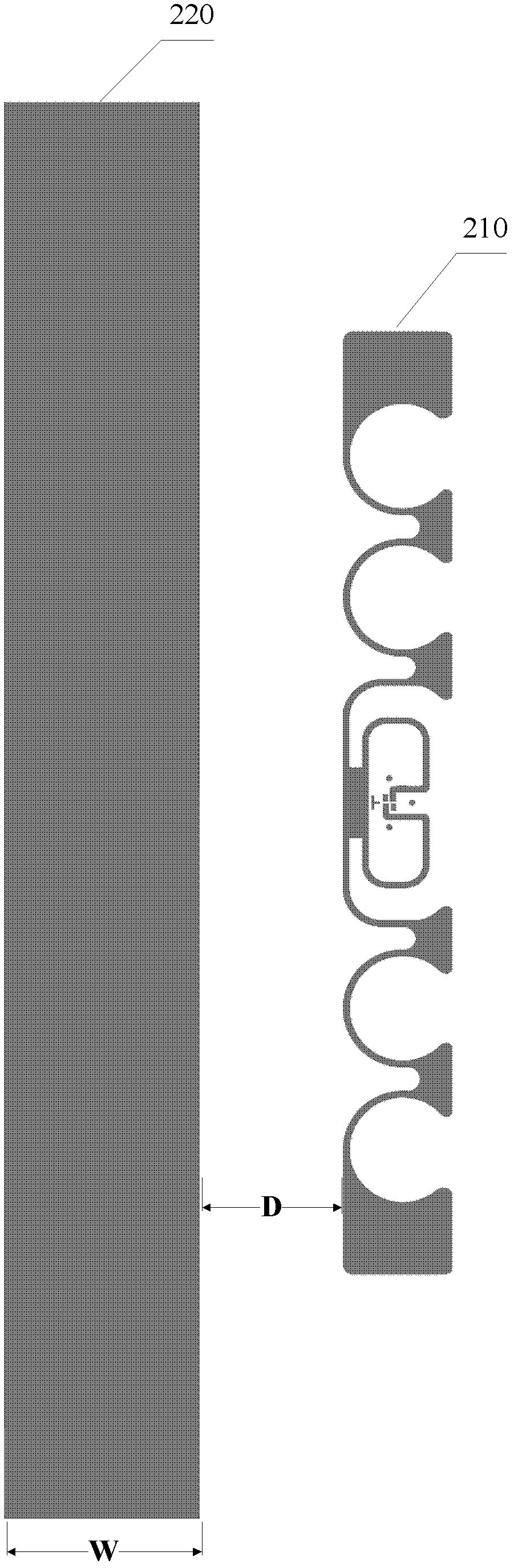
[0043] Please continue to refer figure 2 , it can be seen from the figure that the reflector 220 is rectangular, and its long side is along the direction of the antenna.

[0044] It should be noted that when the reflector 220 gets closer to the antenna 210, the front-to-back gain difference will become smaller and smaller, and the applicable frequency range (that is, the frequency band where the front-to-back gain difference is greater than a certain threshold) becomes narrower, and the gain difference These two parameters, frequency range, are more and more sensitive to the surrounding environment (that is, when the surrounding objects move or the material changes, these two parameters may change sharply). For the widened reflector 220 in this embodiment, generally when the distance D between the edge of the widened reflector 220 and the edge of the tag antenna is less than 10 mm, it is difficult to obtain an ideal unidirectional antenna effect.

[0045] Therefore, in order...

Embodiment 2

[0047] Since the structure of the antenna is not the key of the present invention, the antenna is omitted here for the sake of clarity, and only the structure of the reflector is given.

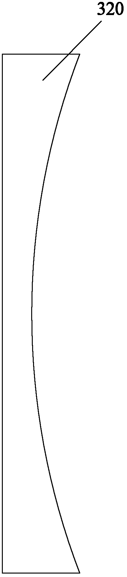
[0048] Please refer to image 3 , the antenna assembly also includes an antenna and a reflector 320. The difference from Embodiment 1 is that the reflector 320 is replaced by a rectangular reflector with a crescent-shaped reflector on one side, that is, the side edge of the reflector 320 close to the antenna is an arc shape. Due to the recess in the middle, the total width of the reflector and the antenna can be reduced while keeping the average distance between the edge of the reflector 320 and the edge of the antenna approximately constant, thereby achieving the effect of reducing the overall size of the antenna assembly. For example, the overall width of the antenna assembly in this embodiment is reduced by about 15 mm compared with the antenna assembly in Embodiment 1.

Embodiment 3

[0050] Please refer to Figure 4 , the antenna assembly also includes an antenna 310 and a reflector 320 , one side of the reflector 320 has a hollow structure 330 . However, the present invention is not limited thereto.

[0051] The main function of adding a hollow structure on the reflector is to increase the equivalent distributed inductance of the reflector to adjust and improve the superposition of the reflected electromagnetic wave and the electromagnetic wave emitted by the antenna itself, so as to ensure that a smaller label size is similar to a large-size label. Unidirectional antenna effect.

[0052] The hollow structure 330 is located on the side of the reflector 320 close to the antenna, and is in the shape of a long and narrow strip, and its direction is substantially parallel to the edge of the reflector 320 on this side. The width of the narrow strip hollow and the distance from it to the edge should be smaller than the average width of the reflector. Specific...


PUM


Abstract

The invention discloses a plane reflector, which is used at one side of an antenna, so that the antenna has a one-way characteristic, wherein the reflector is an axisymmetric structure towards the two sides from a symmetrical axis; and the width of the reflector is increased. Because the reflector is concaved in the middle, the total widths of the reflector and the antenna are enabled to be decreased under the condition of keeping the average distance of the reflector edge and the label antenna edge to be basically invariable, so the effect of reducing the total size of a label can be achieved.

Description

technical field [0001] The invention relates to the technical field of radio frequency identification (RFID), in particular to a plane reflector applied to electronic labels. Background technique [0002] Radio Frequency Identification (RFID) technology is a non-contact automatic identification technology. It automatically identifies the target object and obtains relevant data through radio frequency signals. The identification work does not require manual intervention and can work in various harsh environments. [0003] The RFID system is a simple wireless system used to control, detect and track objects. It consists of two basic devices, namely an interrogator (or reader) and a transponder (or electronic tag). The electronic tag is mainly composed of storage It consists of a large-scale integrated circuit chip with an identification code and a transceiver antenna. The number of electronic tags can be multiple, that is, RFID technology can identify multiple electronic tags ...

Claims


Application Information

Patent Timeline
Patent Type & Authority Applications(China)
IPC IPC(8): H01Q15/14H01Q15/16
Inventor 董培良
Owner SHANGHAI HUAHONG JITONG SMART SYST
Features
  • Generate Ideas
  • Intellectual Property
  • Life Sciences
  • Materials
  • Tech Scout
  • Unparalleled Data Quality
  • Higher Quality Content
  • 60% Fewer Hallucinations
Learn More